3D Precision Beyond the Horizon
Gemini Offshore Wind Farm
The Gemini Offshore Wind Farm in the North Sea is located 85km north of Groningen, The Netherlands. Van Oord, a leading Dredging and Marine Contractor, started the offshore construction work in January 2015. Gemini consists of two separate areas called ‘ZeeEnergie’ and ‘BuitenGaats’, both with 75 4MW Siemens turbines. Gemini will be the 2nd largest offshore wind farm in the world upon completion in 2016, providing power to 785,000 households, equivalent to 1,500,000 people.
Gemini is privately owned by Northland Power (60%), Siemens (20 %), Van Oord (10%) and HVC (10%), and with costs expected to be EUR2.8 billion, Gemini is the largest ever offshore wind farm financed on a project basis.
Project Preparations
The requirements and tolerances for the construction of the Gemini Offshore Wind Farm are described in the ‘Employer Requirements’, used as the baseline document for the preparation of the survey method statements and procedures, which started in January 2014 (Table 1). The tolerance for the position of the foundations, consisting of monopile and transition pieces, was the leading factor in the process of selecting the most suitable method of positioning. Other considerations were: accurate 3D positioning in real-time, hence no need for the post-processing of positioning data and cost efficiency.
By reducing the tolerance for the monopile installation position to 1m radius, the amount of rock to be placed for seabed stabilisation prior to monopile installation could be reduced significantly, thus saving cost and time.
In order to meet the requirements above and in particular the requirement for the Transition Piece flange level, three options were considered, namely GNSS with corrections service such as Fugro G2 or Veripos, seabed tide gauge and the extension of the 06-GPS RTK network to cover the project area.
The feasibility of the network extension was discussed with 06-GPS; by using two offshore platforms as additional reference stations centimetre accuracy could be achieved.
An onshore station in use for subsidence monitoring on the Island of Schiermonnikoog was also to be added to the network.
The Geo++ software used by 06-GPS to calculate and provide GNSS corrections uses the data from the reference stations in the network to model the correction data, providing homogenous accuracy within the network, even if the reference stations are over 40km apart.
Unknown at the time was the influence of platform movements due to wind and waves, as well as the delay in the connection over the internet to the 06-GPS server and then to the user offshore.
Millimetre Accuracy
The Schiermonnikoog station, used by an oil and gas company as a reference for subsidence measurements with mm-accuracy in the Waddenzee area, was added first.
The platform to the east of the project area, Fino-1, a meteo platform for scientific purposes is owned by the German Authorities. Having contacted the operator of the Fino-1 platform, it became clear that a GPS station was already established on Fino-1 and operated by the German RTK corrections provider SAPOS. After upgrading the GPS receiver to include the GLONASS satellites and an upgrade of the connection to shore, the Fino-1 GNSS data were available for use from July 2014.
The platform to the west of the project area, G17d-A, a gas production platform is operated by GDF-Suez. After several meetings with the GDF-Suez personnel responsible for the platform, plans were made to install a GNSS reference station on G17d-A. After installation of the GNSS receiver in September 2014, the network extension was complete.
All coordinates of the new stations are computed using GNSS post-processing software. The system used is ETRS89 and the stations are positioned relative to the first order stations of Active GNSS Reference System (AGRS), maintained by the government of the Netherlands. The platform based reference stations showed some more movement than traditional onshore reference stations, but not more than +/- 1cm, which is acceptable for both the network processing as well as the desired RTK accuracy. The locations of the antennas on the two platform based stations are not as good as on normal onshore stations. Both locations have obstacles like masts and stacks, resulting in fewer available satellites and a more challenging multipath environment than normal. The delays in the connections over the internet were typically smaller than one second and thus within the three second limit for the network software.
On 6 November, interference from an unknown source was experienced at the G17d-A station. Investigations eventually pointed to a connection from the platform to another platform, activated around that time. The interference problem was mitigated by replacing the GNSS antenna by another type in December 2014.
Hydrographic Survey and Installation Operations
For the execution of the survey scope of work on the Gemini project, a charter was arranged with GeoPlus for the Geo Focus, a 35m hybrid survey / ROV support vessel. Mobilised with POS-MV and SeaBat 7125 through the moon-pool and using PDS survey software, survey operations commenced on 5 January with the in-survey of the export cable corridor. The depths were referenced to LAT in the survey software by using the GEONZ97 Geoid model combined with the MSL to LAT model (2006).
In-survey operations continued up to the end of March, combined with trench dredging progress surveys as well as other types of surveys. The correlation between surveys executed over a period of time showed that the repeatability of the positioning was typically better than 5-10cm in X,Y and Z. This could be seen when comparing surveys over seabed features like boulders and gulleys.
In February 2015, two concrete position check blocks, Ø 180cm and 60cm high, were placed on the seabed in the wind farm. The purpose of the blocks was to provide a bench mark for the rock installation vessel coming from Norway, eliminating the need to come to shore for a position check. The comparison of the position check objects’ coordinates established by the Geo Focus by means of a multibeam survey and the coordinates measured with the Fall Pipe ROV systems were carried out prior to every rock installation trip to verify the proper functioning of the vessel’s survey systems.
A ROV was mobilised on the Geo Focus for ROV video and cable burial surveys at the same time. During the first ROV position check on one of the two objects, it was confirmed that there was a bundle of chain on top, which was later removed. The position check objects were also used for checking third party ROV positioning as well as side-scan sonar checks.
Monopile installation was only permitted after 1 July, at the end of the porpoise breeding season, when the porpoises and their young have left the area. For this installation operation, the jack-up installation vessel moves into the desired jack-up position whilst in ‘Dynamic positioning’ mode. It then jacks up, i.e. elevates the vessel out of the water while standing on the ‘legs’. Once all the load tests are completed, a monopile is picked up and inserted into the ‘Gripper’. Using the ’Gripper’, the monopile is moved exactly into the design position. Three systems are used to measure the verticality during the installation process, Inclinometers in the hammer, one or two total stations and Fugro InclinoCam. The combination of the three systems resulted in accurate and efficient installation of the 150 monopiles. The installation level of the monopile is measured and monitored using a total station, set up on a known offset, which was dynamically coordinated using the GNSS-RTK system. All stations to monitor the installation process were set up on rigid pillars welded on deck. All the stations were referenced to a pre-installed prisms. Almost all of the small movements were compensated by the total station compensator. The hammering of the pile had to stop for the measurements to take place.
As soon as the monopile installation started, a back-up reference station was mobilised on one of the central monopiles in both ‘ZeeEnergie’ and ’BuitenGaats’. Powered by solar power, they transmit corrections via telemetry radio.
Results
In our mode of operation, the Virtual Reference Station (VRS) corrections were optimised for the first position update to the 06-GPS server. The position of the VRS remains the same until the connection is reset and re-initialised. Having found out that the data quality was better when operating close to the VRS position, the surveyor was instructed to reset the VRS connection regularly. In order to remind the surveyor of this, the BPQ (Base Position Quality) message from the Trimble receiver was interfaced to the survey software in order to calculate a distance between the vessel and the VRS position. When the distance exceeded 10km, an alarm was generated, prompting the surveyor to take action. Re-initialising the GNSS receiver was typically finished in the time required for taking a sound velocity profile, this then became the standard operating procedure.
The position check objects have been used regularly to check the Multibeam system(s) and the ROV positioning. A trend has been visible in the data, the blocks are slightly deeper than when placed, possibly due to erosion and/or settlement.
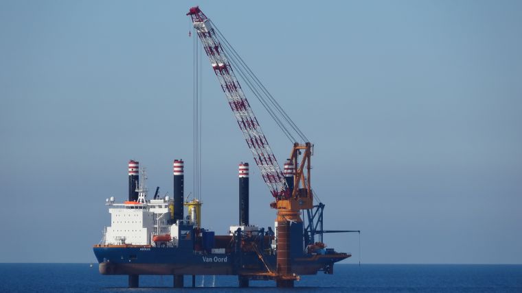
A comparison was carried out on the offshore installation vessel Aeolus whilst it was jacked up. One receiver was set to static measuring mode, the other one to dynamic, both receivers using the VRS corrections. In static mode, the antenna is assumed not to be moving, providing some improvement in accuracy compared to dynamic mode.
The comparison showed the noise present in the Z component of the measurements, but also shows that there is horizontal movement when jacked up caused by wave action on to the legs.
Another comparison was carried out on the Aeolus, whilst it was jacked up, comparing positions derived by using VRS corrections and positions derived by using local base station corrections (Table 2). The average of the two is within a centimetre, however, the position derived with local base station corrections is more stable, as is shown in the standard deviation.
All monopiles were installed well within planning and within the required tolerance, except for one, which was installed lower than the design due to an offset not being applied.
Conclusions
The positioning using the VRS corrections worked very well, there was no downtime due to the positioning accuracy or 06-GPS server failure. The real-time position was accurate and repeatable, shown time and again in the checks and progress surveys. Overall performance of the network extension is illustrated by comparing the RTK positioning results using the RTK network with those from a local reference station placed on a monopile nearby. Because of the large distance between the platform stations, but mainly because of the obstacles on the platforms themselves, the RTK results from the RTK network solution are less accurate than the results from using the nearby reference station. But results were still acceptable and within the specifications for the survey and installation work.
Due to the use of the vessel internet infrastructure and onboard GNSS receivers, it has been cost effective. Once a local reference station is installed and used, it provides a more stable position in the immediate area of the reference station.
More information
www.vanoord.com/activities/gemini-offshore-wind-park
geminiwindpark.nl

Value staying current with hydrography?
Stay on the map with our expertly curated newsletters.
We provide educational insights, industry updates, and inspiring stories from the world of hydrography to help you learn, grow, and navigate your field with confidence. Don't miss out - subscribe today and ensure you're always informed, educated, and inspired by the latest in hydrographic technology and research.
Choose your newsletter(s)


