AUVs in Hydrography
Integrating Autonomous Underwater Vehicle Capability into Hydrographic Operations
The US Navy and the Naval Oceanographic Office (NAVOCEANO) are committed to realising the vision that Autonomous Underwater Vehicles (AUVs) are available, affordable, and can play a critical role for many applications. Working in partnership with NAVOCEANO and the Office of Naval Research, the Remote Environmental Monitoring UnitS (REMUS) was developed at Woods Hole Oceanographic Institution and has improved positional accuracy due to newly developed technology. NAVOCEANO recently procured a REMUS 600 with a commercial shallow-water multibeam system onboard that meets the stringent accuracy requirements for hydrographic applications. NAVOCEANO hydrographic survey missions can now be augmented by LBS-AUV operations. However, the hydrographer must understand how AUV-relevant parameters affect the data collection scheme.
Major advances in technological and payload sensor quality have greatly increased the positional accuracy of the AUV. From a transducer mounted on a surface vessel (e.g., High Precision Acoustic Positioning System (HiPaP)), the Ultra-Short Baseline (USBL) system can be used to position bottom transponders and initiate AUV positioning. Once initiated, precise acoustic navigation is accomplished with state of the art Underwater Transponder Positioning, or UTP. An advantage to UTP is that one or more transponders may be deployed, contrasted to Long Baseline (LBL), which requires a minimum of two transponders, preferably more. UTP transponders can be placed within the survey area instead of peripherally as in LBL. Tight integration between the UTP range measurements and the vehicle inertial navigation system (INS) significantly improves the real-time position accuracy.
DVL-Aiding
Without constant known position fixes from global positioning systems (GPS) or a reference station, an INS must be used to meet positional accuracy requirements. An independent and reliable measurement of the actual vehicle velocity is required to aid the INS in detecting and mitigating its inertial measuring unit (IMU) velocity error. A Doppler Velocity Log (DVL) provides this input and makes DVL-aiding a critical component to the LBS-AUV equipment suite as DVL-aided INS is a key factor to positional accuracy.
Manoeuvring and Cross-Track Drift
Empirical tests show that manoeuvring also has a significant impact on the IMU velocity error. The lawn mower pattern survey-line layout has an order of magnitude less position error, both along and across track, than a long straight line. Consequently, turns can be programmed into the line layout when the accumulated drift becomes greater than the allowed cross-track error (amount of lateral drift from the main line). Verification trials of the real-time navigation processor show that the drift rate is on the order of 0.1% (or better) of the distance travelled. When planning, the hydrographer must consider the position drift rate as it is a key parameter in determining survey-line length and must be determined for each AUV survey system.
Real-time and Post-time Position Solutions
Two critical tools used to ensure accurate positioning are the onboard navigation processor and the navigation post-processing suite.
The real-time navigation processor provides complete time synchronisation and integration of onboard navigation and environmental sensors and can be remotely initialised, monitored, and supplied with surface position updates via acoustic modem from the USBL. In addition, the navigation processor uses tight coupling between the INS and UTP as well as navigation and environmental sensor inputs to calculate the current best present position.
The navigation post-processing application implemented in MATLAB® uses positioning and velocity measurements before and after a given time to make the most accurate post-processed solution through the optimal smoothing algorithm implemented in the Kalman filter. Post-processing the navigation is necessary to refine the real-time positions to achieve the required positional accuracy.
Vertical Sounding Corrections
Tidal fluctuations are a well-known contributor to error in shallow-water bathymetry surveys. Observed tide measurements from land-based tide gauges are not always available to an AUV mission. Alternatively, GPS tide measurements extracted using ellipsoid-referenced survey (ERS) techniques may help satisfy the requirement for applying water-level corrections to sounding data from surface vessels. Unfortunately, the AUV’s lack of continuous ellipsoid height observation complicates the issue. To remedy this, virtual tide corrections (VTCs) from a GPS buoy, a wave glider, or a nearby surface vessel can be computed and extrapolated to the AUV soundings. NAVOCEANO is testing various methods for sounding corrections by calculating a VTC from ellipsoid height observations.
Mission Planning
The overall mission is a set of multiple sorties. Each sortie includes the vehicle movement and conduct from launch to recovery. For proper survey planning, it is critical to understand the role of myriad mission and sortie parameters, which includes the following:
- Altitude from the bottom and resultant swath width
- Bottom lock
- Currents
- Endurance of the battery
- Frequency of vehicle position updates
- Frequency of transponder re-positioning
- Location, spacing, and number of UTP transponders
- Maximum allowable position drift
- Number of lines and turns
- Number of sorties to complete the mission
- Oceanographic conditions
- Orientation of lines
- Position drift rate
- Speed of advance
Other planning parameters will depend on the vehicle’s configuration and positioning system.
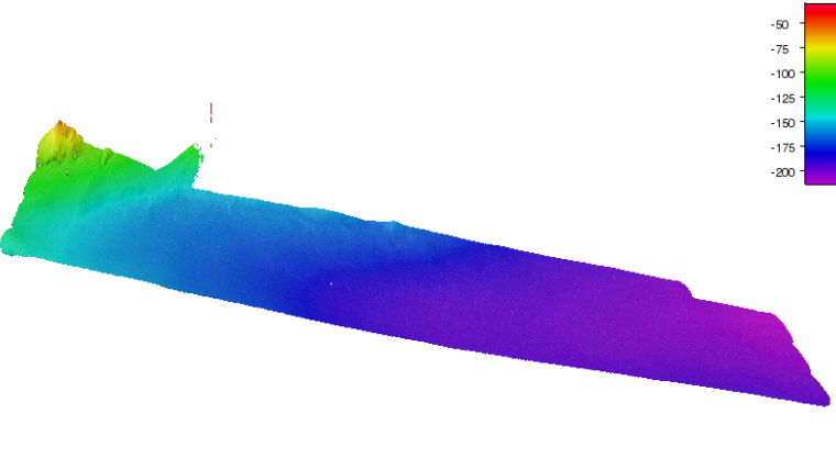
The AUV is very efficient at data collection because it can keep a constant altitude, thereby eliminating swath-narrowing data gaps. The optimum altitude is as high as possible for a wider swath but is limited by the distance that both the DVL and multibeam sonar can maintain bottom lock. Figure 1 illustrates a REMUS 600 multibeam swath collected over depths ranging from less than 50m to over 200m. The constant altitude results in no data gaps. For this reason, the orientation of lines during an AUV survey has more flexibility than the line direction for a surface vessel, which is oriented parallel to the contours.
If the real-time position drifts too far from the planned track, excessive corrections may be needed. Post-time position analysis will help improve estimation of the required position update frequency. This makes the cross-track position drift rate a key parameter in mission planning. The surveying agency will determine the maximum allowable position drift, which greatly affects the transponder spacing and quantity. As shown in Figure 2, transponders are located so that real-time position updates are provided before the vehicle can stray beyond the maximum allowable cross track drift. Additionally, the vehicle drift can be impacted by the direction and strength of currents. Orientation of survey lines and vehicle speed can be strategically used to overcome the influence of currents and help lessen the vehicle drift.
The UTP transponder manufacturer indicates a fix can be obtained within a 2km radius of the transponder in most environmental conditions. In reality, oceanographic conditions will impact the acoustic communication distance between vehicle and transponder; this will vary in each survey area. Figure 3 illustrates survey-line layout for a sortie when the number of transponders is two and the 2km communications radius is achieved. The survey-line length is determined by the Hydrographic Office-determined allowable cross-track drift and survey positioning requirements.
A major limiting factor on the amount of data collected in a single sortie is the battery endurance. Data collection is restricted to several hours less than the battery life to allow for vehicle deployment, recovery, and CTD data collection. Figure 4 illustrates the layout of a main-line sortie that can be accomplished before the vehicle must be recharged. In this example, the number of lines is calculated and spaced 120m apart. The layout in Figure 4 is relative to the swath width that can be obtained at the altitude for DVL and multibeam bottom lock while allowing for a 10% overlap in the multibeam sonar outer beams.
Successive sorties can be run until the lateral distance from transponders reaches maximum reliable acoustic communication, at which point the transponders must be moved for another set of sorties. Multiple sorties may be stacked to reduce the amount of transponder repositioning as demonstrated in Figure 5.
The number of sorties planned to complete a mission area will be determined by considering all the parameters discussed above.
Quality Control
A cross-line sortie is collected before main lines so that data are available for comparisons as the mission progresses. Systematic errors are more likely to be discernible during cross-line data comparisons. A single sweep of cross lines oriented 45 to 90 degrees from main lines can span multiple AUV deployments as depicted in Figure 5.
Conclusions
The US Navy has invested in and committed to unmanned capabilities, and NAVOCEANO is its flagship for implementing this technology. The applications for unmanned operations are numerous and range from navigation hazard inspections, to under-ice surveys, to areas where surfacing or support from a surface vessel is not feasible. The science and capability of LBS-AUV operations is an exciting new area of expansion for hydrographic applications at NAVOCEANO and provide hydrographers with opportunities to apply previous knowledge of mission planning and data collection to new applications and techniques.
The views expressed in this paper are those of the authors and do not necessarily reflect the official policy or position of the Department of Navy, Department of Defense, nor the US Government.

Value staying current with hydrography?
Stay on the map with our expertly curated newsletters.
We provide educational insights, industry updates, and inspiring stories from the world of hydrography to help you learn, grow, and navigate your field with confidence. Don't miss out - subscribe today and ensure you're always informed, educated, and inspired by the latest in hydrographic technology and research.
Choose your newsletter(s)


