Echo Sounders versus Air Bubbles in Research Vessels
Lessons from Experience
Within echo sounding circles it is well known that air bubbles may have a negative effect on echo sounding systems. This article briefly presents the German way of dealing with air bubbles from sweep-down and cavitation processes as well as our experiences with the last three large research vessels (RVs Polarstern, Meteor and Maria S. Merian). The practical experience resulted in the development of an optimised new hull form for the replacement of RV Sonne. The new ship is now under construction at a German shipyard and will be delivered in autumn 2014.
The basis of all echo
sounding systems is the directed transmittance of sound into the water at different frequencies and the recording of its reflection through suitable receivers. The reflection (echo) occurs at boundary layers e.g. within the water column, at sediment surfaces or fishes. Even boundary layers within the sediment can be recorded in this way. Naturally, any air or other gas bubble within the water possesses a rather sharp sound-reflecting boundary layer too. So, as long as there is only water through which the sound is travelling, everything is fine and records are worth reading. But as soon as air or any other gas (e.g. methane) in the form of small and large bubbles (size range might be between less than 1mm to more than several cm) gets in the way of the sound, it is stopped and/or redirected. No or only bad echo sounding records are the result. Hereinafter, all ‘gas bubbles’ are referred to as ‘air bubbles’ for easier reading.
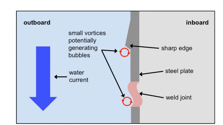
Two quite different sources of air bubbles exist: (1) Obvious are the bubbles from the water surface. With increasing wind and wave action more and more air is mixed into the uppermost water layers. By observing the water surface, whitish water with enclosed bubbles can be seen. Also, as ship movements accelerate, these bubbles are transported along the sides and finally underneath the hull with the installed echo sounding transducers. This process is called ‘bubble sweep-down’. (2) More hidden are the bubbles from cavitation processes hereinafter called ‘cavitation bubbles’. Actually, as the science behind this phenomenon is obscure and not fully understood, the following description is more a theory, than a proven fact. ‘Cavitation bubbles’ come into existence when small and even very small vortices exist, e.g. at sharp edges or weld joints. The water may show different pressures on a small scale within these vortices. The capability of water to dissolve air depends on its actual pressure (this phenomenon is well known from pressure cookers). So, if the pressure changes abruptly at these edges, air may be released in the form of bubbles. Especially, when seawater is air saturated or even air supersaturated, bubbles ‘spring’ into existence. This is shown schematically in Figure 1. This phenomenon is well-known from ship propellers where it is normally avoided by a ‘cavitation-free’ design.
In general, any given problem has several and sometimes quite different solutions. These differences may reach into the field of philosophy. Why should it be different when dealing with the problem of ‘echo sounders versus air bubbles’? The philosophy in Germany concerning the installation of echo sounding transducers is to keep them as close to the bottom as possible. Thus, the optimal solution would be a flat hull and a flush installation. Actually, in most German research vessels echo sounding transducers are installed as far as possible to the front and within a box keel (height between 50 and 70cm) enlargement.
Lessons Learnt from RV Polarstern
Polarstern is an ice-breaking research and supply vessel (length: 118m, width: max. 25m, draught: max. 11.2m). Launched in 1982, she mainly works within the Antarctic and the Arctic and also supplies the German Antarctic station. One of the most impressive features of the ship is the ratio of underwater length and width. In a dry dock she looks like a huge duck. From ice-tank model tests it was predicted that no ice whatsoever will reach underneath the ship. Practice killed theory and after just the first cruise into Antarctica the ship’s bottom looked like an old washboard with huge dents in the steel plates between the rips. Although rather large pieces of ice made their way down underneath the ship, during normal cruising no air bubbles interfered with the echo sounding systems. The systems were installed within a box keel of about 70cm in height.
So, lessons learnt: (1) do not trust all aspects of tank model tests and (2) if a ship is deep enough or even unusually deep, no bubbles will normally reach underneath the bottom.
Lessons Learnt from RV Meteor
Meteor (length: 97.5m, width: max. 16.5m, draught: max. 5.6m) is a globally operating RV. She came into service in 1986 as one of the most modern RVs at the time. She has been working mainly within the Atlantic Ocean and its marginal seas, the East Pacific and the Indian Ocean. During the planning phase, attention was paid: (1) to developing a hull form that would prevent any air bubbles reaching underneath the hull and disturbing the function of the echo sounding systems, (2) towards an optimal hull form regarding energy consumption at maximum as well as normal travel speeds, (3) to limiting draught to about 5 metres, so the ship would be able to carry the German flag even into small and shallow harbours. Numerous tank tests were carried out to make sure all these different tasks were fulfilled. The bubble sweep-down tank tests gave satisfying results. The resulting hull form was characterised by a huge bulbous bow. The big surprise during the first sea trials: echo sounding systems worked poorly or not at all. It became clear, that lots of surface air was trapped within large eddies on both sides of the bulbous bow and swept down the ship’s sides. Figure 2 shows this phenomenon for a ‘normal’ container vessel on its way through Kiel Canal. Installation of cameras below the ship clearly revealed carpets of air bubbles being swept underneath the ship. Naturally, the bulbous bow had to be cut off and replaced by a different one. Figure 3 shows the bows before and after conversion. Furthermore, echo sounding transducers were placed within a lateral extension of the box keel (height about 50cm) as seen in Figure 4. The new bow and the new installation resulted in a slightly reduced speed but also in echo sounding devices that worked.
So, lessons learnt: (1) do not trust all aspects of tank model tests, (2) bulbous bows do not fit with echo sounding systems and (3) integrating echo sounding transducers into an enlarged box keel away from the hull bottom is a solution that works.
Lessons Learnt from RV Maria S. Merian
Maria S. Merian (length: 94.8m, width: max. 19.2m, draught: max. 6.5m) began service in 2006. She was designed according to the experiences of Meteor. From the very beginning there were no questions about a bulbous bow as the ship was intended to be an ice-margin vessel. She had to be able to manoeuvre between ice-flows and to break ice. So, an ice-bow was required. Again all tank tests promised no air bubbles would ever reach the bottom. Surprisingly, the first sea trials revealed that all echo sounding systems refused to give decent results. As camera systems were installed underneath the bottom, again they presented huge carpets of bubbles passing by. As there was no bulbous bow, the source of the bubbles had to be within the bow itself, namely as ‘cavitation bubbles’. The typical icebreaker bow had a large rectangular iron rod fixed in the front to make the first ice-contact. This rod featured sharp edges on both sides. Other edges and unevenness, but less sharp, existed at the depth numbers and other markings. Especially, the edges of the iron rod at the bow supposedly produced cavitation bubbles during cruising. Not everybody involved was convinced. But there was no other logical reason and/or possibility for the echo sounding system failures. So, the sharp edges of the iron rod were cut off and ground down. Furthermore, the whole front part of the bow was smoothened. The situation before and after can be seen in Figure 5. The next sea trials with similar sea conditions and ship movements as before produced good echo sounding results.
So, lessons learnt: when constructing a research vessel’s bow, avoid any sharp edges and unevenness where small vortices could build up and produce cavitation bubbles.
General Conclusions on Air Bubbles
(1) bubble sweep-down:
- bulbous bow should be avoided
- echo sounding systems should be positioned as far to the bow as possible
- echo sounding systems can be installed in an enlarged box keel
(2) cavitation bubbles:
- their production and appearance is actually not yet fully understood and thus less predictable (e.g. the installation on RV Meteor of a retractable bow thruster with edges directly underneath the bottom did not produce cavitation bubbles)
- nevertheless, any sharp edges at the bow part should be avoided; it should be as smooth as possible
- furthermore, creation of cavitation bubbles can also produce noise
at different frequencies, which
may interfere with any acoustic devices.
Hull Design for RV Sonne
The ‘old’ RV Sonne with a hull age of nearly 46 years is to be replaced. The new Sonne will be a deep-sea research vessel (length: 116m, width: max. 20.6m, draught: max. 6.6m) thought mainly to operate in the Pacific Ocean and its adjacent areas. The largest echo sounding array had to be considered (0.5° x 1°beam-opening, transducers length and width about 16 and 8m respectively). Naturally, all the experiences from former research vessels had to be taken into consideration. Furthermore, the results of a discussion that took place in 2010 during a workshop on ‘Optimisation of Research Vessel Design for Acoustic Sensors’ at the 23rd International Research Ship Operators Meeting were kept in mind. At the time, a hull form was emphasised that would channel surface born air bubbles from bubble sweep-down far along the sides. They would then only reach the bottom behind the installed transducers. This led to the development of a new hull form (see Figure 6). The hull exhibits a ‘dent’ along each side to channel the surface-originated air-water mixture far behind the installed transducers. Below this dent, all transducers, huge and small ones, are arranged within a kind of integrated gondola. The avoidance of cavitation bubbles is assured by smoothing the whole front part of the bow. This applied mainly to welding joints.
To date, only ‘normal’ tank tests and computer simulations could be carried out. Both showed bubble sweep-down behind the last crossbeam of the multibeam array (see Figure 7). And although tank test results should be regarded with some caution as noted above, they are still the tool most used for predicting hull performances.
Naturally, the first sea tests to be held early 2014 are eagerly awaited, to see whether practice will be consistent with theory this time.
Acknowledgements
The experiences and advice of numerous persons contributed to the design and construction of the RV Sonne. Many thanks to them, in particular to the technicians and scientists of the Scientific-Technical Advisory Committee, the Federal Waterways Engineering and Research Institute (Hamburg) and the Meyer Shipyard (Papenburg). This project was founded through a BMBF-project 03F0653I (Federal Ministry for Education and Research).

Value staying current with hydrography?
Stay on the map with our expertly curated newsletters.
We provide educational insights, industry updates, and inspiring stories from the world of hydrography to help you learn, grow, and navigate your field with confidence. Don't miss out - subscribe today and ensure you're always informed, educated, and inspired by the latest in hydrographic technology and research.
Choose your newsletter(s)


