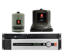
GIB Portable Tracking Systems
The underwater use of GPS
Why has a new positioning system been designed? What are the requirements? What are the drawbacks of traditional solutions? Why are a new concept and system architecture necessary? What applications are addressed? What performances can be achieved?
In the field of underwater positioning, many solutions exist and people are often satisfied with the traditional solutions they are used to. LBL and USBL are widely used for underwater positioning in various applications, though they present some installation and calibration constraints and operational limitations. Their performance can be over estimated and in some cases are not justified. If you push surveyors towards a new positioning concept you will need to convince them that the new technology has significant advantages over traditional solutions within the specific operational context. One also has to prove that the announced performances are achievable under real operational environments. During 1995-96, ACSA designed and had manufactured a prototype which showed the excellent level of performance which could be delivered by a new concept of GPS Intelligent Buoys (GIB). Further, this concept was licensed to ORCA-Instrumentation and is now sold as a product called the GIB portable tracking system. Such systems are now in use with much success in many navies and commercial organisations. The fields of application for GIB systems keep increasing; as does the number of satisfied users. Before describing some of the applications of the GIB tracking system, let us first remind ourselves of the reasons which have driven ACSA to design a new and an innovative architecture.
Positioning Requirements
GPS is widely used for land and air positioning but cannot be used directly underwater. There is a strong requirement for having an underwater system with the same level of performances and as easy to use as GPS:
- An On/Off system
- Requiring no calibration
- Offering a metric accuracy in longitude, latitude and depth
- Improving the ratio: dive time / overall time on site
- Reducing the acquisition and maintenance costs
- Able to position divers, vehicles, fixed structures etc, in various environments
Another challenge is the ability to position simultaneously different vehicles or objects on the same site.
Traditional Solutions Drawbacks
Short baseline and long baseline systems are commonly used for underwater applications but they have their own limitations. Short Base Line:
- The acoustic propagation conditions (thermoclines, etc) can create shadow zones and thus reduce considerably the beam pattern (sometimes at vertical offset angles as low as 30°)
- The system is installed on a dedicated ship and needs to be precisely calibrated during dry docking
- Absolute positioning accuracy depends on additional expensive sensors (ship's digital gyro, vertical reference unit, bathycelerimeter, etc)
- Poor signal to noise ratio due to ship's self noise
- Errors introduced by hydrodynamic vortexes around transducers
- Accuracy of acoustic positioning is quoted as a percentage of slant range at a noise level that can only be achieved in calm weather and without ship motion
Long Base Line:
- Complex system to deploy
- Large seabed arrays of expensive equipment
- Operational ship's mission time consumed for deployment/calibration/recovery
- Conventional system require comprehensive calibration at each deployment
- Many problems of deployment in areas with significant variations in seabed topography
- multi-mobiles positioning decreases repetition rate
- high complexity of system and long delay (10 to 20 seconds) if the submarine or AUV positions have to be known in a surface control room
Non-traditional Approaches
New solutions are located at the intersection of mature technologies and new requirements. In some cases, it is difficult to introduce innovative concepts, precisely because they are 'Not Traditional'. Users express their requirements as a continuous evolution of what was previously known. What happens if the new solution is revolutionary? It simply requires a little bit more time, some education and demonstration. More difficult is the task of the research engineer to whom more and more technologies are offered. The system's architecture design becomes of prime importance.
Designing a New Architecture
The architect approach starts from a clear requirement defined in term of mission objectives. The real question is: which system architecture will provide the expected performances at the lowest cost? Another question raises: who is to know the vehicle's position - the vehicle itself or the surface control unit when one is used (which is the case in 90% of the applications today)? Does the vehicle require X-Y positional knowledge in order to navigate? Will a heading setting, updated at regular interval be sufficient? A system will be a choice of a certain amount of components assembled together in an intelligent way. The role of the architect is to select the components, in some cases to create them, to give them intelligence (what data will be processed and how), to define the data flow from one object to another one (what will flow and when) etc.
Generally, a good system will be one which observes the following rules:
- Performs the mission efficiently
- Limits the number of objects used
- Optimises local processing
- Reduces data flow to a minimum
- Optimises chronograms
- Avoids any sensor calibration requirement
- Keeps the man in the loop
- Allows a remote view of the objects
- Minimises system cost
- Keeps the system simple stupid (KISS)!
GIB Principle and Architecture
The GIB (GPS Intelligent Buoy) portable tracking system was developed by ACSA and is based on a network of surface buoys that measure the travel time of acoustic signals emitted by a pinger mounted on a AUV, ROV, diver (see Figure 1). Every cycle (typically 1 second) the acoustic source transmits two successive signals, one synchronous to GPS time and the other delayed proportionally to the depth. Each buoy measures the GPS time of arrival of those two signals and transmits this information together with its own
D-GPS position to the control and display unit (radio link). The propagation time is directly converted to the pinger/ buoy distance by knowing the sound velocity. As the depth is precisely known (measured on each buoy), the position of the acoustic source is given by the intersection of circles having a radius equal to the projected slant range onto the horizontal plan. The positions of the buoys are known in WGS-84 coordinates and so is the acoustic source position.
GIB Components
The GIB systems are composed of:
- A set of 4 to 12 buoys. Two designs of buoy are available, one small (15 kg) for coastal areas and one spar buoy (6m height, 60 kg) for offshore operations
- Acoustic pingers. The frequency range of pingers compatible with GIB systems ranges from 8 to 50 kHz.
- One control and display unit (a laptop, deck unit containing all the necessary electronics and three antennas)
System Deployment
The system is very easy and fast to install, typically half an hour. The control and display unit requires the installation of three antennas: GPS, D-GPS and radio antenna. The buoys may be anchored or drifting over the mission site. They are operational as soon as thrown in the water.
Applications
The items tracked by the GIB system range from small black box pingers up to military submarines. The speeds range from 0 to more than 50 knots for the GIB-FT system. The GIB systems have been demonstrated in various environments, such as harbours, shallow water, open waters up to depths of 1500 metres. Developments are being carried out for deep offshore operations using the GIB positioning system, up to depths of 2,500 metres. GIB systems are very useful for one-day operations, or for applications occurring in various locations for which the installation of an LBL would degrade the ratio dive time / overall time on site. GIB systems use one way only acoustic paths. As a consequence, they offer a high refresh rate and a very stable unfiltered position information. Those two characteristics offer the opportunity to couple the GIB system with a 3D virtual reality display to provide the pilot of the underwater vehicle (ROV) with a 3D display of the underwater scene. It has been proven to be a major improvement for the guidance of the vehicle, especially in poor visibility waters.
GIB Performances
GIB positioning is very stable and accurate in three dimensions (see other illustrations). The real-time quality control helps the operator to analyse the data and to check the proper functioning of the system. The metric accuracy is claimed by the manufacturer however, the sub-metric accuracy is very often achieved, as shown on the following picture. The pinger was carried by a small ROV, the depth was 10 metres. The unfiltered tracks are very stable and accurate as shown on the following picture. During this trial with the Dorado AUV from ISE, the towfish Aurora was tracked by the GIB system.
Conclusion
The GIB System is the first and only system to offer true real-time GPS tracking underwater. The main advantages of the GIB system are:
- Fast installation on board non dedicated ships
- Easy to deploy & recover, no calibration
- Real-time multi-mobiles capabilities
- Metric accuracy in 3D and accurate positional time stamping
- High repetition rate
- Fully operator-configurable functions
- Real-time quality control
All these reasons explains why GIB systems are now in service within numerous Navies and commercial organisations: USA, France, Canada, Italy, Germany, Portugal, etc. They perform extremely well in various underwater applications such as:
- Oceanographic applications: (research, biology, aquaculture, topography, coastal environment, etc) using
- ROVs, UUVs, (unmanned underwater vehicles) or with divers
- Military applications: torpedo tracking, mines warfare, (detection, localisation, neutralisation), divers' guidance in hostile environment and training
- Salvage and recovery: (distress submarine, rescue operations, recovery of scientific apparatus, black boxes, weapons, lost sonars, AUVs (autonomous underwater vehicles)
- Survey applications: (offshore, oil industries, harbour installations positioning, pipeline positioning, minesweeping, accurate deep towed sonar positioning from ships of opportunity

Value staying current with hydrography?
Stay on the map with our expertly curated newsletters.
We provide educational insights, industry updates, and inspiring stories from the world of hydrography to help you learn, grow, and navigate your field with confidence. Don't miss out - subscribe today and ensure you're always informed, educated, and inspired by the latest in hydrographic technology and research.
Choose your newsletter(s)


