GPS/Acoustic Seafloor Observation
Crustal Movement Around Japan
GPS/Acoustic Seafloor geodetic observation technique has made notable progress over recent years. Positional precision better than several centimetres has been attained through tremendous efforts to improve accuracy in both software and hardware. Some remarkable results have been obtained: intraplate crustal velocity off the Pacific coast of NE Japan caused by subduction, and co-seismic displacement associated with an earthquake in 2005 off Miyagi Prefecture.
Background
The idea for GPS/Acoustic combination technique to measure seafloor crustal movement dates back to early work done by scientists at the Scripps Institution of Oceanography in America. They started geodetic observations using this technique on the Juan de Fuca plate in 1994 and reported, though still preliminarily, the result of detecting plate motion on the seafloor in this area. Japan Coast Guard (JCG) has been carrying out GPS/Acoustic seafloor geodetic observations since 2000. The primary purpose of our observation is to detect and monitor crustal deformation caused by subduction of the oceanic plate near the plate boundary around Japan, where huge earthquakes repeatedly occur. A brief summary of our system appeared entitled ‘Seafloor Geodetic Observation’ in issue December 2003, Vol. 7, No. 10 of this journal. We here report recent results obtained from our observations, together with some descriptions of data analysis methods.
Measurement System
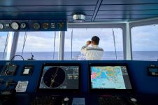
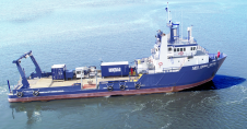
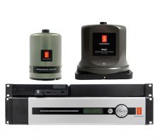
The system consists of a seafloor unit with four (sometimes three) acoustic mirror-type transponders and an onboard unit with GPS receiver and undersea transducer installed on a rigid observation pole of about 8m in length, to which a dynamic motion sensor is also attached. Survey vessels with a gross tonnage of about 600 tons are used. The seafloor transponder receives a ranging signal from the onboard transducer and then transmits the signal back. The ranging signal is a 10kHz acoustic wave, coded with maximum length sequence (M-sequence). The acoustic ranging signals transmitted out and received back by the transducer are both recorded in digital form at a sampling frequency of 200kHz. Kinematic GPS data are mostly sampled at 2Hz. The acoustic wave velocity profile in the seawater, necessary for transforming travel time into distance, is obtained from CTD/XCTD and XBT measurements.
Data Analysis
The data analysis consists of three procedures: (1) kinematic GPS analysis, (2) acoustic wave analysis to obtain round-trip travel time between onboard transducer and seafloor transponder from recorded waveforms, and (3) a combination of results from (1) and (2) to obtain the precise position of the seafloor transponder.
As the first step, positions of the onboard GPS antenna are determined. Because survey areas are in most cases at sea, far from the coast, close reference stations for GPS analysis are usually unavailable. Thus JCG has introduced kinematic GPS software specifically designed to eliminate errors appearing in the long-baseline cases caused by spatial lack of homogeneity in the ionosphere and atmosphere. We estimate errors included in the kinematic result for the vessel by comparing a one-minute average of the GPS-determined sea-surface height with mean sea-surface level, which usually gives a precision of several centimetres. This error estimation also helps avoid adopting degraded results from bad-quality data.
Onset Times
The second step is acoustic wave analysis, which determines round-trip travel times of measured acoustic waves from recorded waveforms: in other words, it identifies the exact onset times of transmitted and received waves. The onset time of an acoustic wave signal is identified by cross-correlation between original ranging signal transmitted and return signal. In this method, the onset of the signals can be identified as a maximum peak in correlograms, taking advantage of the characteristics of the M-sequence code. This method is easily implemented on a computer system and makes it possible to precisely identify onset time, even given a certain degree of background noise.
The last step estimates the position of each seafloor transponder from the successive positions of the onboard transducer and the corresponding round-trip travel times of the acoustic waves, taking into account sound velocity structure. We apply a theory of Bayesian least-squares inversion for the numerical algorithm. This estimates the position of each of the three or four transponders on the seafloor and then finally takes their average as the virtual position of the seafloor reference station. The sound-velocity profile in seawater is given from the temperature and conductivity observed with CTD, XCTD and XBT. However, errors included in the given sound velocity are usually significant considering the required accuracy and one of the major error sources in this technique. In order to overcome this problem we try to estimate the sound velocity as a numerical parameter to reduce the included error together with the seafloor positions. This method enables us to attain a final precision of several centimetres.
Results
Offshore of Miyagi Prefecture in NE Japan lies one of the most active seismogenic zones in Japan. Here the continental and oceanic plates are considered strongly coupled to each other. In September 2001 JCG installed seafloor transponders to form a seafloor reference point labelled ‘MYGI’ (short for Miyagi) in the area. Due to the background sketched above and in order to evaluate the precision of this technique, an intensive campaign of observations has been conducted at MYGI. We analysed the data at MYGI during the period May 2002-Aug 2005. The result is shown in Figures 3 and 4. The reference position for the time-series shown in Figure 3 is the Shimosato site in Wakayama Prefecture, central Japan, which is the JCG Satellite Laser Ranging station as well as one of the ITRF stations. Adding the intraplate velocity at Shimosato (about 3cm/year towards WNW) to the trend of the time-series, the velocity vector of MYGI was obtained as 7.3cm/year in a direction N60_W relative to the stable part of the Eurasian plate as shown in Figure 4. The rms error is about 2cm. Considering that the velocities relative to the Eurasian plate are about 3-4cm/year at the Pacific coast close to MYGI, and that the velocity of the Pacific plate relative to the Eurasian plate along the Japan Trench is 9-10 cm/year, the obtained vector shows consistent direction and the intermediate magnitude between them. This supports the conviction that the obtained vector successfully represents actual crustal motion and implies strong interplate coupling in this region.
Earthquake
On 16th August 2005 a large earthquake (Mw7.2) occurred on the plate boundary off Miyagi Prefecture at a depth of approximately 40km. Its focal region was fairly close to a site labelled ‘MYGW’ (short for Miyagi West) and about 60km away from MYGI. Comparing the measured positions at epochs before and after the earthquake, an eastward co-seismic movement of about 10cm was detected at MYGW, while no prominent movement was found at MYGI. Figures 5 and 6 show the time-series of estimated positions at MYGW and the displacement vector, respectively. Figure 6 also shows the synthetic displacement vectors at MYGW and MYGI under a rectangular fault model proposed by the Geographical Survey Institute of Japan as estimated from its data at GPS network stations. The observation results are consistent with the synthetic displacement vectors. Such information on co-seismic seafloor crustal movement provides valuable information for detailed discussion of slip distribution at the source fault.
Concluding Remarks
While some technical issues remain, JCG seafloor geodetic observation has already arrived at a practical level, if not yet entirely sufficient in terms of positioning accuracy. Stability in accuracy, as well as efficiency in system operation is still a problem. This is emphasised when considering the maintenance of a network consisting of a large number of seafloor stations that must meet societal expectations from the viewpoint of disaster prevention. Further refinement of the system design using the latest technology is required.

Value staying current with hydrography?
Stay on the map with our expertly curated newsletters.
We provide educational insights, industry updates, and inspiring stories from the world of hydrography to help you learn, grow, and navigate your field with confidence. Don't miss out - subscribe today and ensure you're always informed, educated, and inspired by the latest in hydrographic technology and research.
Choose your newsletter(s)


