How to Save Time in Offshore Survey Operations
Bring an AUV Along and Double the Work
In many instances, offshore survey work is carried out in connection with the construction of, for example, pipelines. The operational scenario is often a string of events where one task has to be completed before the next can be started. This article outlines the increased capabilities of an offshore survey or construction vessel when a small autonomous underwater vehicle (AUV) is added to the survey spread, thus enabling it to do double the work. The AUV is launched and recovered from a drawer in the skid of a work-class remotely operated vehicle (ROV).
This concept is designed tobe used with the Gavia AUV, since this AUV is the only one on the market that is small enough, still depth-rated to 1,000m, lightweight and modular.
The AUV’s standard equipment includes a GPS, wireless ethernet link, acoustic modem and an Iridium satellite phone link. For offshore use, the modem can be exchanged with a combined modem and ultra-short baseline (USBL) transponder based on Sonardyne’s wideband technology.
The positioning system consists of a Kearfott T-24 inertial navigation system (INS) aided by a 1,200-kHz RDI Workhorse Navigator Doppler velocity log (DVL).
In the survey version, this AUV is equipped with a wide-swath bathymetric sonar, a down-looking camera, a depth sensor and a sound velocity sensor.
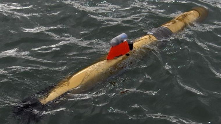
In this configuration, it is only 2.7m long with a 20-cm diameter and weighs approximately 75kg in air. Since most work-class ROVs are about 2.6m long, this AUV will not restrict its manoeuvrability.
The wide-swath bathymetric sonar is a GeoSwath Plus 500kHz (GeoAcoustics Ltd). The wide swath width in shallow water and co-registered side-scan makes this sonar an ideal package as an AUV bathymetry system.
The GeoSwath Plus has been shown to provide high-accuracy, high-resolution bathymetry capable of exceeding International Hydrographic Office (IHO) specifications, along with co-registered side-scan data. This is now proven technology.
Launch and Recovery
In order to make the launch and recovery of such a small AUV as safe and problem-free as possible, the AUV will be placed in a drawer in the skid of the ROV. The design of the drawer has focussed on maintaining the full manoeuvrability of the ROV. A typical work-class ROV can contain a drawer in the skid is normally used for tools for the ROV during operations.
The advantages of having the AUV fixed in a drawer during launch and recovery are many, for example: land recovery system of the ROV is a well-proven technology, and it is safe and efficient. The AUV can be ballasted slightly negatively buoyant allowing it to rest on the seabed when awaiting recovery after the mission is complete. This prevents it from coming to the surface, where it can be a safety hazard and may be difficult to find and recover. ?SBltSIhtWhen the AUV is locked in the drawer, connection is established to the wireless ethernet link as long as the antennas are close enough together. This enables full communication with the AUV via the ROV umbilical and it enables the downloading and uploading of data, mission plans, etc.
The main components of the AUV’s positioning system are the INS, GPS and DVL. On the surface the INS is aided by GPS positioning, and when working at the seabed it is aided by the DVL. When the INS is not aided, the drift rate is higher. Therefore, when the AUV reaches the seabed and the DVL acquires bottom lock, the positioning system has accumulated a ‘dive error’, which shall be corrected prior to launch.
The design of only the drawer of the skid has been modified to include the AUV. In addition, the skid had to be extended slightly in height, by 15cm.
A hydraulically operated locking device is added in order to keep the AUV safely secured in the locked position in the drawer.
One of the design criteria was to ensure that the ROV manipulator is able to position the AUV back in the drawer in one movement, i.e. without having to grip the handle twice. In the image, the ROV-friendly handle is shown slightly darker, just in front of the modem and the tower.
Operational Scenario
In order to ensure that the AUV stays close to the seabed, it will be ballasted to approximately 0.5kg negative buoyancy.
When reaching operational depth and once the accuracy of the AUV’s positioning system has been updated, the AUV can be launched, for example, while the ROV is still attached to the tether management system. The drawer is simply opened and, when the mission plan has been uploaded to the AUV, it can be executed and the AUV will swim out of the drawer and start the planned survey work.
Upon completion of its survey mission, the AUV will land on a designated spot on the seabed. From here, the ROV will pick it up by grabbing the specially designed ROV-friendly handle with its manipulator and carefully lay it back into the drawer, which, when fully opened, extends out approximately 1.4m in front of the ROV so that this can be completed in one movement of the manipulator.
When the drawer is closed and communication with the AUV is established, the recently collected survey data can be downloaded while the ROV continues its mission.
Case Studies
Two actual offshore operations have been analysed, focussing on how much time could have been saved if such an AUV had been included.
The first case was the survey support for a vessel ploughing three 38-km long trenches. While thesurvey vessel and ROV were following and positioning the plough, the AUV could have been sent back 1–1.5km at a time to do the bathymetric survey of the new trenches.
The second case was the survey support for a pipe-laying vessel during the laying of two 10-km-long flowlines. While the survey vessel and ROV were following the touch-down point behind the laying vessel, the AUV could similarly have been sent back 1–1.5km at a time to do the as-laid survey of the new pipeline. The digital camera mounted in the nose of the AUV in conjunction with a bank of LEDs mounted under the ‘tower’ of the AUV will provide images of sufficient quality and number to produce a video of the pipeline and surrounding seabed.
In both cases, the survey vessel could have saved approximately 30% of the actual time used in the field.
Further Developments
Smaller ROVs
The development of recovery tools for smaller ROVs is already in progress with several manufacturers. When using a smaller ROV as a launch and recovery tool for the AUV, the only operational change is that the AUV should be sent off on its mission immediately after reaching the designated working depth, in order not to restrict the ROV in its manoeuvrability.
Positioning Post-processing
Positioning accuracy will be enhanced via a post-processing software package. This software does a lot more than just back-propagating error. The ideal navigation data post-processing and quality control solution for a commercial offshore survey version of Gavia will be based on ‘optimum aided INS Kalman smoothing’. Basically, all the raw sensor data (IMU, GPS, DVL, pressure depth and USBL/LBL if available, etc.) will be re-processed forwards and backwards in time, after which the results are combined statistically to form the optimum navigation result.
Metrology
Tests are scheduled to verify that the relative positioning accuracy is at a centimetre level within a distance of 70–100m. This will be enabled via a combination of the Gavia positioning system, the camera, the post-processing software, a single seabed transponder and the principle of synthetic LBL, as described by Mikael B. Larsen in 2002.
Auto-tracker Module
In order to enhance the capabilities of the AUV to follow a pipeline or a trench, or basically a linear feature on the seabed, an auto-tracker unit has been constructed by SeeByte Ltd and Hafmynd and is currently undergoing sea trials. The unit is processing the side-scan sonar signal online, thereby providing input to the AUV’s autopilot system when a linear feature is detected. It will also search for, acquire and re-search/acquire pipes/rock dumps that are broken or buried, etc.
Conclusion
This AUV has several features that enable its use as described, and these are mainly the accuracy of the positioning system, the depth rating and its small size.
The concept of bringing an AUV along in a drawer under an ROV can be used in a wide variety of offshore operational scenarios including
- Pipeline route surveys. When operated in conjunction with the ROV performing the video survey, the GeoSwath on the Gavia will enhance the end result with wider swath bathymetry and co-registered side-scan
- Pipeline pre-lay surveys. Send the AUV along ahead of the lay vessel
- MBE survey. When the AUV is operated alongside the ROV, the double swath can be achieved.
- Rock-dumping vessels that carry a ‘free-flying ROV’ will have the potential for saving about all their time used on survey in the field.
The only way to save substantial amounts of time in offshore/near-shore marine operations is to add the capability of multi-tasking. One such possibility is described here.

Value staying current with hydrography?
Stay on the map with our expertly curated newsletters.
We provide educational insights, industry updates, and inspiring stories from the world of hydrography to help you learn, grow, and navigate your field with confidence. Don't miss out - subscribe today and ensure you're always informed, educated, and inspired by the latest in hydrographic technology and research.
Choose your newsletter(s)


