Hydroelectric Power Plant Inspections
Using Imaging Sonar
In Brazil there is a legal requirement to inspect all hydroelectric dams and power plants (HPP) every five to ten years, but the methods to be employed for such inspection are not well-defined. Most of the work is currently done by autonomous scuba divers using visual and conventional direct methods. However, there is considerable pressure to reduce the use of diver deployment in such a dangerous work environment. Due to very low visibility the confidence in these surveys is relatively low with much time required to accomplish an inspection. In cases where extended monitoring of the presence of fish near turbines in turbid water is necessary, an acoustic technique such as imaging sonar is needed to accomplish the desired objectives.
The objectives for an HPP inspection can be summarised as follows:
- Identification and location of specific targets, such as lost tools or parts that could inhibit or degrade the operation of any component of the HPP.
- Inspection of broad areas for maintenance, usually related to the civil structure (concrete) in spillways and runoff channels with the objective of identifying structural problems indicated by cracking, exposure of reinforcing bars, areas of concrete spalling (flaking), misalignment at joints, and undermining and settlement of these structures.
- General inspection and monitoring normally associated with critical operational issues such as debris accumulation on water intake screens which may cause flow restriction.
- Assessing environmental issues around inventory and monitoring biota and its relationship with the generating process (i.e. assess the effectiveness of fish ladders or quantify fish injury/survival rates in the hydro turbine passage).
ARIS Explorer 3000
Imaging sonar for the implementation of HPP services must satisfy certain requirements: it must operate at high frequencies to enable discrimination of small features in the target image, it must also have a high image refresh rate to allow a reasonable time to survey the desired area and the software must allow review and post-processing. The acoustic camera, based on multi-beam imaging sonar systems, fulfils these requirements. For this study, several inspections were performed in sites in Brazil, Latin America and Africa usingSound Metrix’s’ ARIS (Adaptive Resolution Imaging Sonar) Explorer 3000 imagery.
The ARIS is the second generation of Identification Sonar and records the intensity of the returned acoustic energy using colour mapping. It can operate on one of two frequencies (LF: 1.8 and HF: 3.0MHz) and has acoustic lenses that form 128 very narrow beams of nominally 0.25. The acoustic lens introduces some non-linearity in beam spacing such that the beams are spaced slightly farther apart at the centre of the image, and slightly closer together at the edges of the image. The maximum down-range resolution is 3mm for both frequencies. The maximum frame rate is about 6fps at LF with a range up to 15m, and about 14fps at HF with a range up to 5m when using all 128 beams or double that when in 64 beam mode.
DL - Detail Level
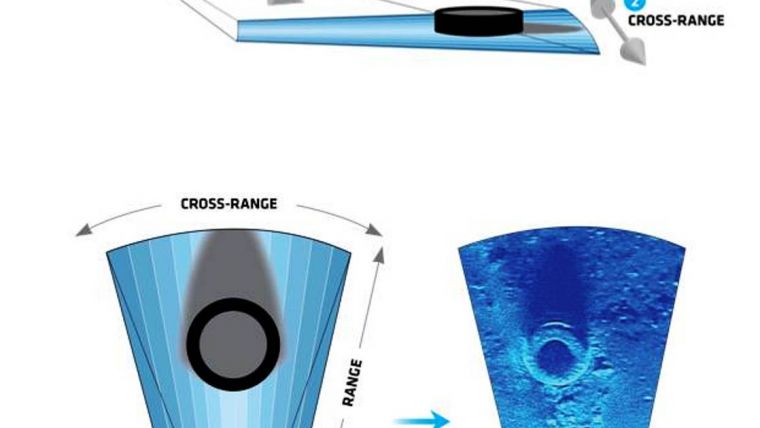
The sonar must be oriented to project beams with a small grazing angle to the surface of interest. The resulting image appears as viewed from angles between the projected beams and the surface (Figure 1). Since the majority of dams have not been designed with fixed structures from which to deploy underwater equipment, a major part of an inspection project must include designing a deployment scheme. A supporting frame can be used in conjunction with a remotely controlled rotator device or the sonar can be deployed from a boat or ROV. The position of the deployed sonar in relation to the target and the used frequency lead to what we describe as the three ‘Detail levels (DLs)’ (Figure 2):
- DL1 for resolution of one centimetre or less using HF. In this case the sonar should not be farther than 1 or 2m from the target and the deployment platform must be quite stable. If the visibility conditions are favourable, it is possible to use an optical camera simultaneously. The image window coverage area is typically 1m2 or less.
- DL2 provides nominal resolution of a few centimetres (typically 5cm or less) at a distance of 3 to 4m. Both frequencies can be used depending on acoustic conditions. This configuration strikes a good balance between resolution and covered area. With an image window in the order of 5m2.
- DL3 is recommended when it is necessary for overall imaging of larger areas with reduced resolution (up to 20m2 per image window) using LF at distances of 10 to 15m from the target. It may be possible to mount the sonar near the water surface depending on the total water depth.
Mode of Operation
In the inspections we did DL1 was used extensively for concrete assessment where cracks and faults serve as an early warning of structural problems (Figure 3). For monitoring purposes or other inspection requirements where long-term imaging is necessary, the sonar can be attached to a fixed structure such as a telescopic extension arm and operated as visual support for technical manoeuvres or periodic maintenance.
Concrete inspections can also be performed at DL3 from a boat when looking for larger scale features such as fracturing or erosion in spillway floors, downstream channels or tailraces. When using a boat, the survey needs to be done in the short periods when the turbines are idle or the spillway closed. If the sonar is not fixed on a structure a motion reduction filter should be applied to stabilise the image and improve data quality.
The most frequent type of survey is the assessment of trash rack and intake conditions in detail level 1 and 2. The survey conditions surrounding trash racks can be quite challenging due to high current flow, extensive structural areas and low to no optical visibility. In these scenarios we used the ARIS integrated on an ROV and fixed on a telescoping extension arm. In the latter case it was possible to visualise the water intake process in real-time during operation, allowing the observation of debris accumulation that was obstructing the trash racks. This validated numerical models of head loss related to percentage blockage.
Conclusion
Hydroelectric power plant environments, normally associated with turbid waters, have complex inspection needs and frequent requests for underwater inspection and maintenance services. Imaging sonar has proven to be effective with the performance of the sonar depending on the proper combination of deployment (fixed mount, boat mount, ROV integration, and optional rotator), orientation of the sonar (grazing angle, distance) and the settings of the sonar (frequency). When properly conducted, imaging sonar surveys could bring considerable advantages in terms of safety, accuracy and costs in comparison with current methods of visual/scuba diving inspections bringing innovative and cost-effective solutions for such strategic and complex areas as Hydro power planning, construction and management.
More Information
- Belcher E.O., Matsuyama B. and Trimble G.M. 2001 Object identification with acoustic lenses. Proceedings of Oceans 2001 Conference; 5–8 November; Honolulu, Hawaii. 2001. p.6-11. Marine Technical Society/IEEE
- Holmes, J.A., Cronkite, G.M.W. Enzenhofer, H.J. and Mulligan T.J. 2006 Accuracy and precision of fish-count data from a “dual-frequency identification sonar” (DIDSON).imaging system.ICES J. Mar. Sci. 63(3): 543.
- LaBry, Kenneth J. 2012 Application of acoustic imaging for underwater substructure inspection and mapping. Proceedings of 32nd Annual USSD Conference, New Orleans, Louisiana.

Value staying current with hydrography?
Stay on the map with our expertly curated newsletters.
We provide educational insights, industry updates, and inspiring stories from the world of hydrography to help you learn, grow, and navigate your field with confidence. Don't miss out - subscribe today and ensure you're always informed, educated, and inspired by the latest in hydrographic technology and research.
Choose your newsletter(s)


