Technology in Focus: Insides of Side-scan Sonar
Advancing Technology for a Wide Range of Purposes
Although today’s multibeam echo sounders come with a backscatter option the more traditional Side-scan Sonar (SSS) still has many advantages when it comes to bottom imaging. Over the past years, SSS technology has gone through an evolution rather than a revolution. In this article we will zoom in on the current state of the art of this useful acoustic imaging device.
Detection of Objects and Bottom Structures
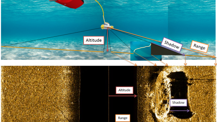
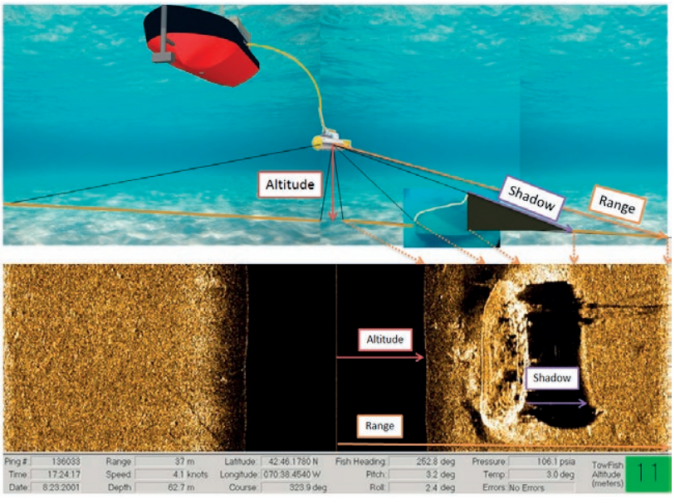
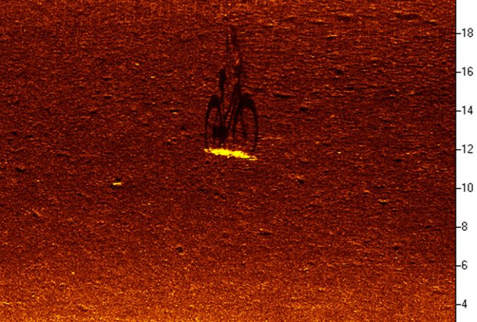
Side-scan Sonar is mainly used for the detection of objects and bottom structures. To obtain those images it digitises a sound pulse sent out from two transducers mounted on each side of the SSS fish. Images are based on the amount of reflected sound energy and presented on a time basis resulting in a continuous image of the bottom (Figure 1).
As a tool it gives very highly detailed images indicating not only the existence of objects but also the type of material (strong reflector or weak reflector).
SSS systems are commonly towed using a 1m to 2m long tow fish, although some manufacturers provide smaller systems of around 0.4m in length as well as pole mounted systems for shallow water where towing would be impossible or ROV / AUV mounted transducers for deepwater imaging.
SSS vs Multibeam Echo Sounders
SSS systems do not provide direct height/depth information; this has to be inferred from the image (object height as a ratio between fish altitude, shadow length and total distance between fish and end of shadow). There are manufacturers providing so-called hybrid SSS / bathymetric systems. In general, these systems provide full SSS images with interferometric multibeam bathymetry.
Multibeam Echo Sounder (MBES)
Conversely, a beam forming multibeam echo sounder (MBES) will provide depths from dedicated transducer arrays allowing for high-accuracy beam discrimination. Nowadays, most MBES systems can also provide backscatter information. The difference between MBES backscatter and a true SSS is that the MBES will provide one backscatter value per beam whereas the SSS will provide an (almost) continuous signal thus giving a higher resolution.
Side-scan Sonar (SSS)
As such, a hybrid SSS is not a replacement for a multibeam echo sounder for high accuracy work and neither is a multibeam with backscatter a replacement for a SSS when it comes to the detection of small objects and/or bottom type differences. There are, however, many jobs where one is more important than the other and the additional information provided is still valuable.
Range
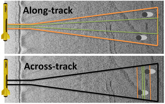
A SSS system is defined by a number of parameters of which the range and resolution are probably the most important. The resolution of the SSS defines the image quality and can be divided in ‘along-track’, ‘across-track’ and backscatter resolution (Figure 2).
The range defines how effective the SSS will be (how much of the bottom can be surveyed in one track). Range is effectively a function of the frequency at which the SSS operates; the higher the frequency the smaller the range (500m @ 150kHz vs 35m @ 1600MHz). Modern SSS often have the option of running two or even three frequencies at the same time, allowing for both a long range (but with less detail) and a short range with high detail without having to switch the system and run multiple survey tracks.
SSS Range Resolution
The across-track or range resolution defines what the smallest distance is between two objects that are ‘behind’ each other in the direct path of the SSS beam. Where in the past the transmitted signal would have been of the ‘continuous wave’ (CW) type, a modern SSS transmits what is called an FM or CHIRP signal (CHIRP = Compressed High Intensity Radar Pulse). The main advantage of the CHIRP is a longer range with better range resolution.
For a CW type SSS the range resolution is defined by the pulse length of the signal whereas for a CHIRP type SSS the range resolution is defined by the bandwidth of the signal allowing longer pulses and therefore more power to be transmitted. For a high-frequency, short range (1600MHz, 35m) CHIRP SSS the range resolution is sub-centimetre allowing very fine detail across track to be shown in the image.
Along-track Resolution of a SSS
The along-track resolution of a SSS is traditionally defined as the product of the so-called horizontal beam angle of the side-scan (typically between 0.2° and 1.5°), the effective range and the tow-speed of the SSS. A small beam angle at short range will allow the detection of small objects spaced apart along the track of the SSS. When scanning for objects 100% bottom coverage is usually required; NOAA specifications state that at least three hits should be obtained from a 1 metre cubed object. As a result there is a maximum speed at which a SSS can be towed before consecutive beams / pings at a certain distance are spaced too far apart to detect an object; for regular SSS systems this is somewhere in the 4 – 5kts region.
Multibeam and Multi-ping
Higher tow speeds can be obtained if more hits were to be obtained from an object. Currently there are two different solutions employed by SSS manufacturers to achieve a higher tow rate (Figure 3).
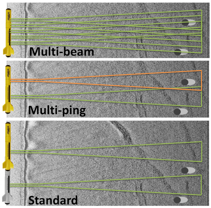
One is to make use of multiple beams. If, for example, 5 beams are used on a single side of the SSS then the effective along-track resolution is multiplied by 5 allowing higher tow speeds. The alternative solution is to have multiple pings in the water. With CW type SSS this is not possible but with the CHIRP type this can be done. If there are two pings in the water for a certain range then the effective tow speed can be doubled as well. Modern multibeam SSS or multi-ping SSS systems can be used at speeds of up to 12kts.
Backscatter Resolution
The last parameter to define the image quality in digital systems is the level to which the received acoustic signal is digitised into a digitally usable signal. In the past, SSS data collection was done on paper where digitisation would not be performed. However, the modern SSS uses digital data transmission over network from the fish to the sonar processor. For this an A/D convertor is used to convert the analogue (A) signal into a digital (D) signal. In digital signals the number of bits used for the signal defines the level of detail that can be captured. The more bits used to do this, the more detail in terms of different types of material / backscatter can be captured. For a modern SSS the signal is captured in between 12 and 28 bits. Although these numbers seem quite low it should be realised that a 24 bit SSS can capture over 16 million different shades of grey where a 12 bit ‘only’ captures 4096 shades of grey. In comparison, a modern digital camera captures around 12 – 16 bits per colour channel.
SSS Options
All SSS will provide a backscatter image as that is the main purpose of the SSS. The resolution and range will differ from one system to another and is where manufacturers differentiate their offerings. Finally, it is the number of available options that may sway a buyer from one model to another. Some interesting options include a motion sensor, a compass and depth or altitude sensor integrated into the SSS fish allowing for motion correction and a fine adjustment of tow depth.
In select SSS systems the motion sensor is used to dynamically stabilise the beams allowing a continuous (straight) path across the bottom. Some SSS fishes include a water temperature sensor allowing for real-time adjustment of local sound velocity.
Most SSS have an optional tow bracket to tow a magnetometer simultaneously with the SSS whereas some SSS are integrated with a Sub-bottom Profiler allowing complete geophysical surveying in a single track.
An interesting option is a so-called ‘gap filler sonar’, which covers the area directly under the SSS where a regular SSS cannot survey. Such a gap filler would therefore theoretically allow a full bottom image and allow a significant reduction in overlap between SSS tracks.
More information
Huibert-Jan Lekkerkerk is contributing editor and author for other publications on GNSS and Hydrography and principal lecturer Hydrography at Skilltrade. He is also technical manager for the Dutch government. He has worked as client representative on projects such as Maasvlakte 2 and the Ketelmeer environmental dredging project.
Email: [email protected]

Value staying current with hydrography?
Stay on the map with our expertly curated newsletters.
We provide educational insights, industry updates, and inspiring stories from the world of hydrography to help you learn, grow, and navigate your field with confidence. Don't miss out - subscribe today and ensure you're always informed, educated, and inspired by the latest in hydrographic technology and research.
Choose your newsletter(s)


