Error in GNSS Augmented Heading Systems: Influence of Attitude
The Effect of Antenna Height Difference on Heading Quality
My earlier articles on the alignment of motion reference units (MRU) with the ships reference frame (SRF) did not cover the calibration of GNSS augmented heading systems. Although the alignment can be done in the same way as mentioned in the previous articles, GNSS augmented heading systems need special attention regarding their installation. This article will show that the accuracy of these systems may be seriously affected by the vessel’s attitude if the antennas are not installed at the same mutual height above the X/Y plane of the SRF.
The more accurate ROVINS (0.05° x SEC(LAT), which is the accuracy at the equator that deteriorates with latitude, and PHINS (0.02° x SEC(LAT)) have become increasingly popular since the previous articles, and we have been aligning more than a dozen of them, within their specifications.
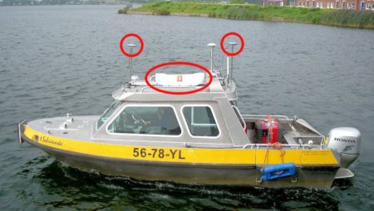
GNSS augmented heading systems (see Figures 1 and 2) have an accuracy that depends on the mutual distance between its two antennas. An accuracy of more than 0.10° can easily be achieved and even 0.02° or more is possible. Alignment can be done in two ways; either by measuring the perpendicular distances between known on board nodes (e.g. the vessel's bollards) and a known reference (e.g. a quay side), as discussed in 2008; or simply by calculating the misalignment from the relative positions of the antennas within the SRF. The accuracy of the latter method depends on the accuracy of the offset survey. With modern survey techniques it should be no problem to achieve a point accuracy of 0.002 metres at a 40 metres long vessel (1σ, 68%). This corresponds to an angular accuracy of approximately 0.04° at a 4 metres baseline between the antennas.
Assuming a coordinate system with the Z-axis upwards, the misalignment θ follows from the following simple formula where L is the horizontal (i.e. parallel to the X/Y plane of the SRF) baseline length between the two antennas:
tan(θ) = dX/L. [1]
Dual antenna GNSS augmented heading systems are either installed with this baseline parallel to the vessel's centreline (see Figure 1) or perpendicular to it (see Figure 2). The former configuration will provide heading and pitch of the baseline, while the latter configuration will provide heading and roll of the baseline. The resulting roll or pitch will be the true attitude of the SRF if the two antennas have an equal height in the SRF or if the angle between them and the X/Y plane of the SRF is known.
Let us suppose that we have a vessel with two antennas along the centreline, therefore having equal coordinates in the direction perpendicular to the ship. According to equation [1] the misalignment would be zero degrees. Let us also suppose a nonzero mutual antenna height difference dZ, combined with a nonzero roll ρ. The higher antenna will be displaced further from the centreline than the lower (see Figure 3). The induced difference between them along this X-axis dXi is calculated as:
dXi = sin(ρ) ∙ dZ. [2]
This attitude induced displacement dXi causes an error in the heading which I call the attitude induced heading error θi. The attitude induced heading error can be calculated by combining [1] and [2]:
tan(θi) = (sin(ρ) ∙ dZ)/L, [3]
which can also be written as:
sin(θi)/cos(θi) = sin(ρ) ∙ dZ/L. [4]
It is assumed that the resulting θi will be small, which means that cos(θi) approaches one. Therefore, [4] can be simplified to:
sin(θi) = sin(ρ) ∙ dZ/L. [5]
If we also assume that ρ is small, and as a consequence sin(ρ) almost equals ρ (expressed in radians), the result is:
θi / ρ = dZ/L. [6]
From [6], it becomes clear that the height difference (dZ) should be kept to a minimum, preferably zero. It also becomes clear that the baseline length (L) should be as large as possible, which is also beneficial for the heading accuracy of the system. Even when the momentary pitch or roll misalignment angle can be fed into the system, the system will not be able to distinguish between attitude induced heading error or an actual heading change. The attitude induced heading error with respect to ratio dZ/L is shown in Figure 4.
The maximum acceptable height difference depends on the role heading plays in the on board system. Except for survey vessels, the maximum allowed induced heading θi,max is calculated using the propagation law of variances from the positioning accuracy (σPos) in combination with the horizontal lever-arm length to the reference position (LLA) and the required accuracy of this reference position (σref):
tan θi,max = sqrt(σref2-σPos2)/LLA. [7]
Equation [7] is of course only valid if the positioning accuracy is better than the required accuracy of the reference position, as it is impossible to increase the accuracy of the positioning system by adding a heading device.
For hydrographic survey vessels the heading requirement does not only depend on the required reference point accuracy, but especially on the installed echo sounder system. Hydrographic vessels should always try to position within their footprint. When using a multibeam echo sounder this does not only account for the head, but the heading accuracy should be within the along-ship bundle width of the multibeam echo sounder to position each sounding within its footprint along the whole swath. Given a typical along-ship signal width of 1° for shallow water multibeam systems, the heading accuracy should thus never be greater than 0.5°, but preferably not exceed half of that (0.25°).
Not all vessels allow easy installation of the antennas within the dZ/L ratio of the examples. In contrast to the examples that assume installation along the ship’s centreline, mounting the antennas in the perpendicular direction has the advantage that the accuracy is affected by the less extreme pitch values. In addition, getting the antennas mounted at the same height above the X/Y plane of the SRF is easier, as vessels are more symmetrical in that direction.
As the acquisition software has knowledge of both attitude and heading of the SRF, it should be a minor issue to extend the heading driver with an option to correct for the attitude induced heading error. The software would need to know the positions of both antennas. One of those is usually the primary navigation antenna, which obviously has a known position in the SRF.
Conclusion
In order to benefit from the full accuracy of GNSS augmented heading systems, attention should be paid to the height difference between the antennas during installation. For survey ships similar to the example given, it is recommended to keep the height difference between the antennas within 2.5 percent of the baseline length. In addition, it is recommended to extend acquisition software with an option to correct for the attitude induced heading error. Such an extension should require only minor changes to the software.
Example for the calculation of the maximum allowed induced heading for regular ships
Let us assume: a requirement for positioning the reference position with an accuracy σref of 0.25 metres; a standard deviation σGNSS of 0.03 metres for LRK-GNSS positions; and a 30 metres lever-arm LLA. With equation [7], this results in a heading accuracy θi,max of 0.5°. Using an expected maximum roll ρmax of 5°, the ratio θi / ρ of equation [6] becomes 0.1 and therefore dZ should not exceed 10 percent of the baseline length between the antennas. As the 0.5 degrees requirement is about ten times the system accuracy of the GNSS augmented heading systems, the influence of the system accuracy itself can be neglected in the calculations.
Example for the calculation of the maximum allowed induced heading for survey ships
It is not unusual for hydrographic vessels to experience a roll ρmax of 10°. Assuming that a maximum induced heading accuracy θi,max of 0.25° would be acceptable at such a roll, the ratio θi / ρ of equation [6] becomes 0.025. Consequently, dZ should not exceed 2.5 percent of the baseline length between the antennas when mounted in the direction along the centreline.
More Information
- de Hilster, 'The MRU and SRF aligned, Part I: Solving the Yaw Angle', in: Hydro International, Vol. 12, Nr. 9 (2008) pp.24-29.
- de Hilster, 'The MRU and SRF aligned, Part II: Solving the Pitch and Roll Angles', in: Hydro International, Vol. 12, Nr. 10 (2008) pp.18-21.

Value staying current with hydrography?
Stay on the map with our expertly curated newsletters.
We provide educational insights, industry updates, and inspiring stories from the world of hydrography to help you learn, grow, and navigate your field with confidence. Don't miss out - subscribe today and ensure you're always informed, educated, and inspired by the latest in hydrographic technology and research.
Choose your newsletter(s)


