Non-linear Acoustics in Echosounding and Sediments
For attaining high-resolution echo-prints, echosounding equipment must fulfil certain requirements regarding directivity, pulse length and other properties possible to achieve using non-linear acoustics. One important problem in sediment acoustics is determination of the thickness of sediment layers. If the sound velocity is known, thickness can be calculated from travel times.
Parametric acoustics, combined with principles of seismic refraction, allow estimation of the sound velocity of selected sediment layers. Non-linear acoustics demonstrates advantages when obtaining frequency-dependent sediment properties, such as the attenuation coefficient.
Sediment echosounders transmit sound pulses directionally to the sea bottom and receive reflected signals both from the bottom and from sediment layer boundaries and embedded objects. The horizontal resolution achieved depends on the area hit by the sound beam. Wide beam width means bad horizontal resolution and the occurrence of diffraction hyperbolas at small structures; wider beam width also causes higher surface and volume reverberation. Vertical resolution depends on the pulse length of the transmitted signal; shorter pulses will result in better resolution.
Short pulses can be transmitted only by systems with a high frequency-bandwidth. The ringing effect at the end of the transmitted pulse depends on the transducer bandwidth and should be as short as possible, especially for echo-sounding in shallow water. Expected penetration depth depends on attenuation of sound in sediment layers, the attenuation coefficient being proportional to the frequency and dependent on type and structure of the sediment. For safe detection of small sediment structures or buried objects the same bottom area must be hit several times to enhance the signal-to-noise-ratio, SNR. In this, as in the case of fast changes in bottom structure, pulse repetition rate should be as high as possible.
To get high-resolution echo-prints from received signals the ideal echosounder for surveying should have:
- Narrow beam width, without side lobes
- Wide frequency range
- Short sound pulses without ringing
- High pulse repetition rate
- Beam steering and stabilising and heave compensation
- Echo-prints calculated in real time
- High mobility and, therefore, small and light equipment
Linear vs. Non-linear Echosounders
Linear echosounders directly generate a sound pulse of the desired frequency. Directivity depends on the ratio of the transducer dimension and signal wave length. There is a main lobe with a certain half-power beam width and side lobes. Side lobes cause echoes from outside of the desired direction. A narrow beam at low frequencies requires large transducers. A given transducer will have differing beam widths at different frequencies.
Non-linear echosounders simultaneously transmit at least two signals, of slightly differing high frequencies (primary frequencies), at high sound pressures. Because of non-linearity in sound propagation at high pressures, transmitted signals interact and new frequencies arise. The so-called secondary frequency (difference in transmitted frequencies) is low enough to penetrate the seafloor. The reflected primary-frequency signals can be used for exact determination of water depth, even in difficult situations, such as soft sediments.
The directivity of the difference frequency is similar to the primary frequency; small transducers can therefore transmit low frequency signals at narrow beams. For different secondary frequencies, the directivity is nearly the same and the sounded bottom area will be of nearly the same size. This is important if echo-prints from differing frequencies are compared. There are no significant side lobes for the difference frequency.
There are no local minima or maxima in the near-field area for the difference frequency sound pressure distribution along the acoustical axis of a circular piston transducer using non-linear acoustics.
This means that non-linear echosounders may be used in very shallow water. Due to the interaction length of the parametric transmitter, the decrease in sound caused by geometrical losses and physical attenuation will be low as compared to linear echosounders and because of the high system-bandwidth of a non-linear system, really short signals can be transmitted without ringing. This is particularly useful in shallow water areas.
Small beam-width and high frequency-bandwidth means that bottom echoes from non-linear echosounders have a steeper slope than echoes from linear ones. These steeper signals are easier to detect at low signal-to-noise ratios, for instance in areas with dredging activity. Detection of small changes in acoustic impedance and high resolution of layers thus become possible and a more realistic and more accurate picture of the bottom layer and sediment structures beneath the bottom will be produced.
With non-linear systems short pulses, narrow beams and the absence of side lobes results in less volume reverberation and less reverberation from the bottom surface as compared to linear systems. This gives a better signal-to-noise ratio, especially in areas with silting.
Non-linear Echo-sounding
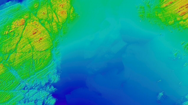
Over recent years a series of mobile non-linear echosounders have been developed achieving very good results both in shallow water areas and in water depths of 1,500m and more. The echo-print shown in Figure 2 represents changes in acoustical impedance between neighbouring sediments in a false colour scale - rainbow colours from blue (small changes) to red (big changes). The visible signal dynamic range is up to 96dB, depending on the signal-to-noise ratio.
Sediment Classification
Some important sediment properties can be estimated for sediment classification, for example sound velocity and attenuation coefficient. The attenuation of compressional waves depends mainly on frequency and porosity of the sediment.
a = kfn; n = 0.5K 2
The parameter n is for most sediment types nearly 1 and k is a material parameter that depends, among other things, upon porosity, grain size, grain-size distribution and viscosity. In Table 1, typical values for sound velocities, attenuation coefficients and parameters k and n are given for various sediment types.
Estimating Velocity
Water depth and sediment layer thickness is calculated from sound pulse travel times. To get the exact layer thickness, knowledge of sound velocity inside the sediment is necessary. The sound velocity can be obtained by core measurements, but a great deal of work is involved in this method and the measurements are fault-prone. The use of parametric acoustics in-situ estimation of sediment layer sound velocity is becoming possible and may reduce the number of core probes. For this purpose, simultaneous sound pulses are transmitted vertically as well as obliquely and sound velocity is calculated from the travel times of both, see Figure 3. Figure 4 gives an echo-plot example and Table 2 contains the determined values. The depth h1 is calculated from the vertical sound beam. For accurate calculation it is necessary to determine hs and hh exactly. Geometry - the distance between transducer and hydrophone streamer and water depth - also influences the accuracy of this method.
Attenuation Coefficient
Another important sediment parameter is the attenuation coefficient, estimated when several frequencies are used for sediment sounding. For this purpose, Chirp sub-bottom profilers are used as a multi-frequency source. But here the sounded bottom area for different frequencies will not be the same as described above. Changes in the received signal will not only represent sediment properties but also the directivity pattern.
Non-linear echosounders are better suited for this task because beam pattern will be nearly the same for all secondary frequencies. Thus changes in the received signal depend directly upon sediment properties.
Figure 5 shows a profile recorded at 6kHz and 12kHz with the same pulse length. The profiling at both frequencies was realised simultaneously with the parametric sediment echosounder SES-96 standard. Alternatively, other simultaneous combinations of frequencies such as 4kHz, 8kHz and 12kHz may also be chosen. In particular for deeper layers, it is clear from Figure 5 that the lower the frequency, the lower the attenuation. If there are two frequencies, as in this example, the attenuation coefficient can be calculated from layer-bottom amplitude ratios at both frequencies. This is only possible on the assumption n=1. Otherwise it is necessary to use more frequencies. For this analysis, multiple echoes also have to be taken into account.
If attenuation coefficients are known, reflection coefficients and the density for these layers can be estimated.
Conclusions
The use of parametric sub-bottom profilers offers the possibility to get online survey results with excellent vertical and horizontal resolutions at acceptable penetration. Short transmitting pulses without ringing permit operation in very shallow water. Despite small transducer dimensions, low frequency signals can be transmitted with a very narrow beam. The sounded area hardly varies through all generated frequencies. The simultaneous use of differing low frequencies allows determination of signal parameters for estimating material properties like sound velocities, attenuation coefficients and densities.

Value staying current with hydrography?
Stay on the map with our expertly curated newsletters.
We provide educational insights, industry updates, and inspiring stories from the world of hydrography to help you learn, grow, and navigate your field with confidence. Don't miss out - subscribe today and ensure you're always informed, educated, and inspired by the latest in hydrographic technology and research.
Choose your newsletter(s)


