Synthetic Aperture Sonar Challenges
Synthetic aperture sonar (SAS) has been under active development for decades. The technique is particularly well suited for autonomous underwater vehicles, and it is expected that SAS will replace traditional side-scan sonars for many ‘high-end’ AUV applications in the years to come. Research systems have been used for more than 15 years and many R&D groups around the world have been able to present images that would not have been possible to produce using traditional sonars. However, in many cases, these impressive sonar images are the result of days of tuning and tweaking by experts. A lot of effort has gone into making SAS work robustly and reliably in adverse conditions in recent years, to the point where the technology has now become commercially viable.<P>
Military users have been thefirst to adopt this new technology. Mine hunting in particular is an area where SAS promises to solve the inherent problem of covering a large area in a short time – with sufficiently high resolution to allow detection and classification of small, low-signature bottom mines. The technology also has a number of other potential uses, including offshore seabed surveying, underwater archaeology, debris mapping, and search and rescue operations.
Background
When autonomous underwater vehicles (AUVs) started to become commonplace in the 1990s, the side-scan sonar soon became a sensor of choice. Traditionally mounted on a towfish, migrating the side-scan sonar to an AUV was straightforward and gave instant benefits. However, when high-resolution imaging is required, the area coverage rate of such a system is severely limited. The far-field side-scan sonar along-track (azimuth) resolution is inversely proportional to frequency and antenna length. Antennas longer than 1–2 metres are difficult to fit on AUVs and high-frequency signals have limited range. For a resolution of say 10cm, the maximum range is limited to around 50m even with high-end side-scan sonars.
Synthetic aperture sonar (SAS) is a technology that allows resolution higher than the most advanced side-scan sonars, with a range up to hundreds of metres. SAS is analogous to synthetic aperture radar (SAR) and shares the same basic principle: the forward motion of the platform is utilised to synthesise a long antenna (and hence improve the azimuth resolution). For this to work properly, the platform needs to move less than one-half the physical antenna length between pings. By moving slightly less, overlapping data can be used to estimate the motion of the platform with extreme accuracy. The maximum achievable range with SAS is thus inversely proportional to platform speed. This means that the area coverage rate is independent of speed and directly coupled to the receiver array length.
The differences between radio waves in air or space and sound waves in water give rise to a different set of challenges in SAS compared with SAR – and different solutions. Most of the core ideas employed in today’s SAS systems were published or patented back in the 1970s and 1980s, with successful physical experiments starting in the early 1990s. Probably the first commercial delivery of an AUV-based SAS was the EdgeTech 4400-SAS on the HUGIN 1000 AUV, delivered to the Royal Norwegian Navy (RNoN) in January 2004. While the system eventually functioned well in benign environments, the main lesson learned from this and other early ‘real-world’ SAS deployments was that further development (in sonar design, hardware and software) was needed to reach the level of robustness and performance required for deployment under challenging conditions.
SASs can be mounted on remotely operated vehicles (ROVs), they can be towed or even hull-mounted, but AUVs have some distinct advantages as platforms for SAS systems. Their size, speed and stability can be made to match the requirements of a SAS system. AUVs also usually operate close to the sea floor, away from the difficult near-surface layers. Finally, AUVs tend to be equipped with a highly accurate navigation system, which is a requirement for the optimal use of a SAS.
HISAS
In 2000, the Norwegian Defence Research Establishment (FFI) and Kongsberg Maritime started a joint R&D project that aimed to design and implement a complete SAS system (hardware and software), as a supplement to the long-standing HUGIN AUV programme. A high-end prototype SAS system called SENSOTEK was installed on a HUGIN AUV in 2004 and has been used in numerous sea trials under varying conditions. The end result of this project was a new series of commercial SAS products from Kongsberg Maritime called HISAS and a complete SAS processing toolbox from FFI called FOCUS.
The first product, HISAS 1030, has two 1.2-m, 32-element receiver arrays and a programmable phased-array transmitter-receiver on each side. The standard operating frequency is a 30-kHz band centred at 100kHz; however, much lower frequencies and larger bandwidths can also be used. The sonar has a theoretical resolution of approximately 2×2cm at all ranges – and up to 200m range at 4 knots, and 260m at 3 knots. Because the sonar is fully interferometric, SAS and side-scan sonar-based bathymetry can be produced in addition to the imagery.
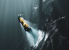
HISAS 1030 is an essential part of the new HUGIN 1000-MR military AUV. Sea trials with the first were started in 2007 and the system is currently being delivered to the RNoN. The vehicle can carry up to 18kWh of energy in pressure-tolerant lithium polymer battery modules, providing about 24 hours of endurance. The result is a per-mission net area coverage in excess of 50km2.
Figure 1 shows the HUGIN 1000-MR AUV during a sea trial in 2007.
Design Choices
Frequencies from 50 to 300kHz have been used in existing designs for seabed imaging with SAS. While the choice of frequency does not necessarily impact SAS resolution or range, it affects the nature of the imagery produced in various ways. Higher frequency yields sharper shadows behind objects and a better real-aperture image. Lower frequency, on the other hand, allows multi-aspect imagery and very-long-range operation at low speed. Also, the back-scatter strength of bottom objects and the seabed itself is frequency-dependent.
One of the often-cited benefits of SAS is the ability to get the same resolution at all ranges. While in principle this is true, it is also a fact that it becomes harder to achieve this as range increases. Signal-to-noise ratio drops, imaging geometry gets less favourable, platform motion requirements become harder to meet and processing requirements increase. To ensure robust SAS operation, design choices must be made to help reduce these difficulties.
SAS Processing
FFI has developed a complete software suite, named FOCUS, for processing SAS data. The FOCUS toolbox delivers a range of products, from rapid results such as dynamically focused side-scan imagery and side-scan bathymetry, via streaming stripmap SAS imagery, to high-fidelity spot products. In addition, highly accurate navigation data are available and can be used as an aiding sensor for autonomous navigation.
Part of the trade-off analysis of integrating a high-resolution SAS in an AUV is deciding what parts of the processing to do in real-time in the vehicle and what to do in post-processing after AUV recovery. The first HUGIN 1000-MR will initially create rapid results in the vehicle. The other products are likely to be migrated after initial delivery. As SAS processing is computationally expensive, this will increase the power consumption and consequently reduce AUV endurance. Thus, the amount of processing to perform in the vehicle is a trade-off between mission endurance and post-processing efficiency.
Ensuring Robust SAS Operation
Several design choices have been made, both in software and hardware, to increase the performance and robustness of HISAS 1030 in adverse conditions. Some of the techniques used are described in the following paragraphs – with examples of the performance improvement obtained.
Shallow Water
Long-range sonar imaging in shallow water will always be limited by multi-path and direct surface returns. Traditional side-scan sonars often have broad vertical beams. The primary problem in shallow water then becomes direct echo from the sea surface, which masks the wanted echo from the sea floor. The phased-array transmitter of HISAS 1030 allows optimisation of the beam pattern for long-range shallow-water performance. This substantially reduces the direct surface return. In addition, SAS processing inherently increases the signal to multi-path level due to the coherent integration in time.
In addition, direct surface returns are seen as a wobbly structure at long range in the side-scan image. This is not visible at all in the SAS image.
Rough Terrain
Coherent reconstruction of SAS images requires knowledge about both the vehicle position and sea-floor bathymetry. An exception to this is perfectly straight synthetic apertures. Norwegian waters often have rough bathymetry, making it almost impossible to run AUVs on straight lines and at the same time have favourable operational conditions for other payload sensors such as multi-beam echosounders. Being an interferometric system, HISAS 1030 collects data for both imagery and bathymetry in the same swath. This improves the robustness for SAS in rough terrain. Figure 3 shows the side-scan bathymetry from the HISAS prototype collected by HUGIN AUV in coastal waters with varying bathymetry in Norway. The inset shows the result after the data from the EM3000 multi-beam echosounder on the same AUV have been added for gap filling. Combined, the two sensors can thus provide bathymetry in a 400-m swath at a speed of 4 knots.
Environment Variability
Synthetic aperture imaging is near-field imaging. To produce high-quality SAS images, an accurate estimate of the sound speed profile is required. In the littorals, the sound speed can vary rapidly. The HISAS 1030 with the FOCUS toolbox uses two different strategies to combat this problem. First, the vehicle can adaptively collect the environmental data needed for an accurate map of the sound speed. Second, the FOCUS toolbox uses adaptive image-correction techniques that estimate and correct for inaccurate environmental data. Figure 4 shows a SAS image collected in the inner harbour of Horten (Norway). The water depth is 13m and the range shown is 45–75m. On this particular mission, the sound speed varied from 1,507m/s at vehicle depth to 1,483m/s at the seafloor. By using the sound speed at vehicle depth, a mild blur degrades the image fidelity. By using the adaptive image correction, the resolution is improved considerably.
Results from Sea Trials
The first HISAS 1030 system has been tested in several sea trials in 2007–2008. In addition, a number of sea trials were conducted with the SENSOTEK prototype sonar in 2005–2006.
The images shown in Figure 5 are from the Factory Acceptance Test of the HUGIN 1000-MR AUV delivered to the RNoN in March 2008. In this figure, the large area shows a 140×140m section of the starboard swath (range 30–170m). The inset is a 30×30m zoom around a sunken fishing boat at 70m range. An acoustic release transponder (float, rope, sandbag) is visible near the bow of the wreck.
Benefits
A high-resolution SAS system such as HISAS 1030 has numerous advantages over conventional side-scan sonar. Some of the most important are:
•very high resolution, allowing reliable classification of mine-like objects over a very wide swath
•high signal-to-noise ratio and wide dynamic range, allowing detection of even very weak targets in areas with strong back-scatter
•multi-aspect imagery: a sequence of images can be formed from a single pass of an object, depicting the target over a 30º range of aspects. As many complex objects have a highly aspect-dependent echo and shadow structure, this gives the operator an extra dimension in the data set
•rapid, full-swath bathymetry, providing good resolution (approx. 1×1m) bathymetric information suitable for, e.g. REA operations. The bathymetry information can also be used to automatically compute the precise extent of shadow zones (areas not covered due to occlusions)
•very-high-resolution bathymetry, allowing classification of targets based on shape/height
•complementary modes of post-processing, for example, processing for maximum shadow contrast or for maximum resolution, from the same data set
•SAS motion estimation produces a highly accurate displacement measurement, which can be used to aid the navigation system. This can reduce position error growth substantially when position updates are not available.

Value staying current with hydrography?
Stay on the map with our expertly curated newsletters.
We provide educational insights, industry updates, and inspiring stories from the world of hydrography to help you learn, grow, and navigate your field with confidence. Don't miss out - subscribe today and ensure you're always informed, educated, and inspired by the latest in hydrographic technology and research.
Choose your newsletter(s)


