Triaxus, a 3-D Underwater Undulating Towed Vehicle
Undulating towed underwater vehicles have been used for a number of years, mainly in the ocean science community, hydrographic industry and by navies. When looking at the systems currently in use, there are several issues and problems to be addressed such as size and weight of vehicle and winch/cable, sufficient space for payload sensors, payload sensor power supply and data transfer, tow cable breaking strength/drag/diameter, 2-D undulation / 3-D undulation.
Undulating towed underwater vehicles have been used for a number of years, mainly in the ocean science community, hydrographic industry and by navies. When looking at the systems currently in use, there are several issues and problems to be addressed such as size and weight of vehicle and winch/cable, sufficient space for payload sensors, payload sensor power supply and data transfer, tow cable breaking strength/drag/diameter, 2-D undulation / 3-D undulation.
Some of the existing systems use large electrical or hydraulic motors to drive the control flaps. This means big heavy metal frames resulting in a relatively heavy vehicle both in air and in water. Furthermore, the large motors leave limited space for payload sensors protected within the vehicle body. In order for a heavy vehicle to obtain an acceptable undulation envelope, especially at relatively low tow speed, the tow cable needs to be faired with hard fairings. This results in a complicated winch and launch / recovery system requiring more deck space and higher power consumption.
Another big issue when designing underwater towed undulating vehicles is the outer shape of the hull. In order to obtain stable attitude of the vehicle, both at high and low forward tow speed, it is necessary that hull design will allow the payload to be installed inside the hull as far as possible. If large payload sensors are installed external to the vehicle hull, it may have a major impact on the vehicle’s performance, especially at high forward tow speed. One way to overcome this is to use a neutral or slightly positive buoyant vehicle design. This will result in a stable attitude behaviour over an extended speed range (2-12 knots) and, depending on the detailed hull design, it will allow generous room for payload sensors inside the hull.
Installing payload sensors on a vehicle should be easy for the user, especially on cruises where the speedy change of sensors for other work tasks is critical for the cruise programme. Another important issue when discussing payload sensor interfaces, is the ability of the system to accept sensors with a high data rate, especially when the user requires real-time data transfer to the surface processor unit for all the installed individual payload sensors. All of the above mentioned features can only be obtained if a fibre-optic transmission and multiplexer systems are implemented. Furthermore, it must be possible to supply all the required AC and DC power to the individual payload sensors from the vehicle control system; and it is also a big advantage to be able to monitor the individual power supplies and even switch each individual power supply line on and off via the control system in order to avoid interference between sensors.
The use of fibre-optic transmission technology is also having a huge impact on the tow cable design, especially on the outside diameter of the cable. The cable will typically have two or three power conductors, two or three optical fibres, all covered with a dual steel armour and the diameter will be typically between 8 and 10mm. By utilising the right armour package design, this cable will have excellent breaking / working strength capabilities as well as low drag coefficient figures.
All of the existing underwater towed undulating systems on the market are based on 2-D vertical undulation (Y and Z), fulfilling most user requirements, but there are various cases where a third dimension (X) is required. One of the obvious applications of using the 3-D undulation, is in shallow water, when undulation directly behind the surface ship will result in distorted data due to the ship’s propeller stirring up the water. In this case, the 3-D underwater towed undulating vehicle can be offset horizontally relative to the ship,
and undulation can take place in undisturbed water. Another application is using the vehicle at an auto depth and then undulate horizontally from side to side to collect data in a certain horizontal water layer. Finally, the 3-D vehicle can be set to undulate vertically and horizontally simultaneously for maximum water column coverage.
System Description
The new 3-D underwater towed undulating system includes the following main elements:
- Surface control unit
- Winch and tow cable
- Underwater vehicle
Surface Control Unit
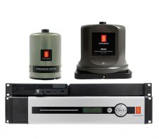
The surface control unit consists of a portable 19" rack system where
all the major topside equipment including the power supply unit, surface control PC, control console, PC interface unit and the Nexus multiplexer is installed.
The Triaxus system is controlled from the topside PC which communicates with the embedded PC in the Triaxus vehicle via the Nexus multiplexer unit.
Control of the underwater vehicle can be manually from the control joystick as well as automatically by using the PC Windows-based control software, which allows the user to set up tow parameters specifying the detailed tow (depth envelope, vertical speed, horizontal offset etc.).
The following tow set-ups are available:
- Auto depth
- Auto altitude
- Simultaneously vertical / horizontal undulation
- Vertical undulation
- Vertical undulation with horizontal offset
- Horizontal undulation
Winch and Tow Cable
In order to achieve the best performance envelope for the system, the tow cable properties are critical, especially the diameter / SWL (Safe Working Load) / cable drag relationship. The Triaxus tow cable consists of two electrical conductors and two single mode optical fibres. This gives an inner assembly of the cable with a small outside diameter, but still a cable with extremely high data capacity because of the single mode fibres. On top of this assembly, there is a dual steel armour bringing the final O.D. up to 9.98mm and a SWL of 15kN. This cable is used without any fairing and still allows a large depth envelope over a big speed range. At the sub-sea end of the tow cable, the mechanical termination bottle is installed. Inside this termination bottle, the electrical / fibre-optic converter is installed, so between the termination bottle and the vehicle, only an electrical cable is used. Integrated in the termination bottle there is a weak link that will break if the vehicle hits an obstacle in the water.
The cable winch used is an electro-hydraulic type with automatic level wind and a capacity up to 3,000m of the above mentioned tow cable. The winch can be controlled both from the control valve on the winch and remotely from the surface control unit.
Underwater Vehicle
The Triaxus underwater vehicle is constructed from carbon fibre with large main foils at the front of the vehicle; four cylinder shaped tubes and four control flaps at the aft of the vehicle.
It is towed from the centre point at the front, and by using the aft control flaps, both vertical and horizontal movement is achieved. In order to maintain the roll of the vehicle at zero degrees, two small control flaps are installed on the middle horizontal foil. These flaps are automatically activated whenever the roll is not zero. The four longitudinal tubes are used for installation of vehicle electronics and payload sensors. The tubes are 1,200mm long and the internal diameter is 220mm. In the upper STB tube 600mm is allocated to the vehicle electronics and in the lower STB tube the battery bottle accounts for 500mm. The remaining room in these two tubes and the entire area in upper and lower port tubes are free for the client’s payload sensors.
Performance
The basic vehicle is designed to operate down to 400m at forward speeds from 2Ð10 knots. Vertical speed can be programmed in the range from 0.1Ð1.5 m/sec, either as triangle shaped undulation with symmetrical slopes or as saw-tooth shaped undulation with asymmetrical slopes. Furthermore, a user specified undulation set-up can be programmed into the topside computer allowing the user to select any undulation pattern required. The vehicle can also be programmed to obtain auto depth as well as auto altitude including bottom terrain following. Programming a horizontal flap angle value and a time before switching to the next horizontal flap angle value, gives horizontal undulation. If an external sensor system, like USBL, DVL or a 2-D current meter is installed, the horizontal movements can be displayed or even used as a reference for the horizontal auto function.
Conclusion
Looking at the growing demands
in the market for underwater undulating towed vehicles, the Triaxus system offers excellent solutions as a relatively lightweight system, 3-D undulation, good performance envelopes and a highly flexible payload sensor integration philosophy based on plug and play. Furthermore, the outline and performance of the vehicle is based on principles used on a number of vehicles designed and built by the MacArtney group over the last two decades.

Value staying current with hydrography?
Stay on the map with our expertly curated newsletters.
We provide educational insights, industry updates, and inspiring stories from the world of hydrography to help you learn, grow, and navigate your field with confidence. Don't miss out - subscribe today and ensure you're always informed, educated, and inspired by the latest in hydrographic technology and research.
Choose your newsletter(s)


