Stop Using DGPS!
The Unsuitability of Non-centimetric Positioning for Shallow-water MBES Surveys
High-resolution multi-beam echo sounder (MBES) surveys should not be conducted where the uncertainty of the horizontal positioning system is larger than the nadir footprint of the MBES at the mean survey depth. In depths of 100 metres, the horizontal component of the nadir footprint of a 0.5 degree by 1.0 degree MBES, is an ellipse whose minor axis is approximately 0.9m, and approximately 0.09m at 10m depth. Regardless of the International Hydrographic Organization (IHO) Special Order Specification that allows for non-centimetric level horizontal positioning, such as Differential GPS (DGPS), the results are unacceptable for high-resolution shallow-water surveys, especially where feature detection is a priority.
You get what you pay for. The availability of DGPS in the mid-1990s, followed by Satellite Based Augmentation Systems (SBAS), offered metre and sub-metre horizontal accuracies at a relatively inexpensive cost. These accuracies enabled hydrographers to easily meet the IHO Special Order Specification for Total Horizontal Uncertainty (THU), which today still allows for a maximum THU of 2m at a 95% confidence level. Despite the non-Gaussian distribution of noise in GPS positioning, the IHO horizontal specification is wide enough that DGPS positioning remains acceptable, yet it should not be.
Chasing the Vertical
With the horizontal positioning component being quickly weighed-off so many years ago, hydrographers have almost entirely forgotten about this important factor as they focus their attention only on the vertical (Z) component of the survey. As a result, MBES manufacturers have given us sonar systems with centimetre level range accuracies. Technological improvements in support equipment such as Inertial Motion Units (IMUs), Sound Velocity Profilers (SVPs), Timing Systems, and Data Collection Systems have all contributed to reducing a survey’s Total Vertical Uncertainty (TVU), which is exactly what we as hydrographers have demanded. However, we have treated the overall reduction in THU as a welcomed by-product of chasing the vertical component without too much afterthought to its impact on improving the quality and accuracy of shallow-water MBES surveys.
Consider the following two hydrographic survey scenarios, both occurring in less than 100 metres of water, both using a high-resolution MBES. In Scenario One, the surveyor uses centimetric level positioning via Real-Time Kinematic (RTK) or Post-Processed Kinematic (PPK) GPS. In Scenario Two, the surveyor uses some form of sub-metre DGPS or SBAS. If you were to ask both surveyors why they chose the positioning system that they did, both would almost certainly touch upon a cost-benefit analysis that they considered relating to the vertical component of GPS. Surveyor one would discuss the advantages of not having to worry about squat, static draft and water levels whereas surveyor two would likely state that the added cost of centimetric (vertical) positioning was not justified as water levels and/or draft were not difficult to obtain and accurately measure. It is highly likely that neither surveyor considered the horizontal component of a centimetric positioning system in their analyses because of the mindset that labels centimetric positioning to be a ‘Z’ value only product.
MBES Footprint Size
The latest generation of high-resolution shallow-water MBESs offer hydrographers 1.0 x 0.5 degree beamwidths (or better) resulting in small horizontal footprints. Table 1 shows that at 100m depth, the minor axis of the MBES footprint is less than half the size of the IHO Special Order THU (2 metres) and at 10m depth, the minor axis of the MBES footprint is 23 times smaller. As we shall see below, using a positioning system whose horizontal uncertainty is significantly greater than the MBES footprint size can adversely affect the results of a shallow-water MBES survey.
|
Nadir Depth (m)
|
Horizontal Footprint Major Axis (m)
|
Vertical Footprint Minor Axis (m)
|
|
5.00
|
0.0873
|
0.0436
|
|
10.00
|
0.1745
|
0.0873
|
|
20.00
|
0.3490
|
0.1745
|
|
30.00
|
0.5235
|
0.2618
|
|
50.00
|
0.8726
|
0.4363
|
|
100.00
|
1.7452
|
0.8727
|
Patch Test Errors
A recent survey of a large harbour in Brazil used an R2Sonic 2024 MBES and an Applanix POS MV 320 V5 GNSS Aided Inertial Navigation System. In real-time, the surveyors used SBAS sub-metre differential corrections and in post processing, they used POSPac MMS for a Smoothed Best Estimate of Trajectory (SBET) incorporating PPK positioning.
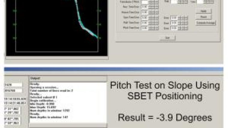
The Roll component of the Patch Test for the survey was conducted over the flat harbour seafloor at 16m depth and the Pitch and Yaw components were run over a slope that rose from 16m to 7m depth. On board the vessel, the Patch Test was analysed in the CARIS HIPS/SIPS Calibration Tool and the Roll and Yaw components matched expected results. The Pitch component however was -12.9 degrees which immediately raised suspicions about the validity of the test. Another set of pitch lines were run over a pinnacle whose base was at 14m depth and whose top was at 10m depth resulting in a value of -13.6 degrees.
When post processing the Patch Test, the Smoothed Best Estimate of Trajectory was calculated in POSPac MMS using a single Global Navigation Satellite System (GNSS) Base Station as the reference. The resulting Horizontal Uncertainty in the X and Y components was less than 7cm. CARIS HIPS/SIPS was then used to replace the original navigation with the SBET navigation and the Patch Test was re-analysed in the Calibration Tool. The Roll and Yaw values did not change however the Pitch value was -3.9 degrees for both the slope and pinnacle surfaces. Figures 1 and 2 show the before and after Pitch calculations using sub-metre differential positioning versus centimetric SBET horizontal positioning. The obvious conclusion is that the entire post-processed survey would have been suspect had centimetric level positioning not been used for the patch test.
Surveyed Feature Misalignment
In May of 2012, a Multi-beam Surveyor Training Course was conducted in Buffalo and the practical survey portion involved a high-resolution MBES survey along a section of the Buffalo River. Substructure Inc’s MV Orion was employed with its R2Sonic 2024 MBES and Applanix POS MV 320 V4 GNSS Aided Inertial Navigation System. Real-time positioning used RTK GNSS corrections; however, the large distance to the base station resulted in the real-time status rarely exceeding ‘Float Wide Lane’ status i.e. decimetric Horizontal Uncertainty. POSPac MMS was used for centimetric post-processed SBET positioning.
The practical survey portion of the training course covered a large area where many small features were detected; however, one feature in particular elucidated the importance of centimetric positioning for shallow-water surveys. The object in question was a hollow vertical pipe 2m in diameter rising approximately 3.5m off the river bed.
In real-time, the two passes over the pipe did not line up due to the decimetric positioning uncertainty. The point cloud in Figure 3a shows the misalignment. The advanced capabilities of the high-resolution MBES were being done a disservice by the decimetric Float RTK accuracy.
As in the Brazilian survey, POSPac MMS was used in order to generate an SBET position but in this instance, the Continuously Operating Reference Station (CORS) GNSS network data were used to create a Virtual Reference Station on top of the vessel position. The resultant Horizontal Uncertainty in the X and Y components was less than 1.5cm. The point clouds in Figures 3b and 4 clearly show the centimetric efficacy after the SBET was applied in CARIS HIPS/SIPS.
Conclusions
Centimetric level positioning is not just for those surveys where the Z component of the GNSS solution is desired. Any high-resolution MBES survey in 100m or less of water should use centimetric X and Y positioning regardless of whether the Z component is being calculated from water levels or GNSS.
Simply stated, high-resolution surveys demand horizontal positioning whose uncertainty is less than or equal to the footprint size of the MBES nadir beam. Using a positioning system whose accuracy exceeds this can result in poor patch test results, poor feature detection, or more frankly, a low quality survey.
IHO Special Order Accuracy allows for a THU of 2m. Clearly this specification opens the accuracy flood-gates in order to let DGPS positioning in, with the remaining horizontal components of other equipment contributing very little to the overall THU. When using the latest generation of high- resolution multi-beam echo sounders for high-resolution (Special Order) surveys, DGPS should not be used.
Note - related to this article, a Letter to the Editor was sent to Hydro International, which has been published in the January-February 2013 issue.

Value staying current with hydrography?
Stay on the map with our expertly curated newsletters.
We provide educational insights, industry updates, and inspiring stories from the world of hydrography to help you learn, grow, and navigate your field with confidence. Don't miss out - subscribe today and ensure you're always informed, educated, and inspired by the latest in hydrographic technology and research.
Choose your newsletter(s)


