Surface Imaging Capabilities on Marine Hydrographic Vessels
In a combined effort of the National Oceanic and Atmospheric Administration and private industry (Applanix and Riegl), two different but complimentary technologies were tested in the marine survey field to find a more efficient, higher-accuracy and safer alternative for traditional shoreline verification methods. This article describes the tests and the encouraging good results with this videogrammetry and laser scanning technology.<P>
Vessel-based shoreline verification is a laborious, exacting and often dangerous element of nautical charting. During this process, a boat is deployed into the near-shore region to verify shoreline information extracted from aerial photogrammetry. Near-shore features such as piers, rocks, islets and aids-to-navigation must all be accurately positioned and attributed for accurate charting. Two technologies, not typically seen in hydrographic surveying, are investigated in this article, namely vessel-mounted videogrammetry and laser scanning. Both hold promise for improving the accuracy, speed and safety with which this work is done. The technology was originally developed for land mobile mapping and terrestrial-based vehicles, and may now be extended to the marine environment.
This means that a suitably equipped vessel can acquire geo-referenced image and point cloud data where all recognisable objects can be attached with a latitude, longitude and elevation.
A survey vessel on location, equipped with videogrammetric technology will be able to map and image geomorphological features, ports, coast lines, waterway infrastructure, bridges, utilities, oil and gas structures, and vessels without placing personnel in harm’s way. In addition, imaging equipment can be used for inventory of waterway assets and in forensic investigations of waterway incidents.
Vessel-based laser scanning will provide return intensity information on those features within each scan. This reflectance can be used to automatically select aids to navigation, which are typically equipped with highly reflective material to reduce the amount of time required for positioning these objects. The point cloud data acquired with the laser scanner will be married with data acquired from the multi-beam sonar systems to create a seamless bathymetric/topographic model of the shore–water interface.?
The combination of videogrammetry with the laser scanning technology will yield unique opportunities for automatic selection based on reflectance and classification based on optical character recognition (OCR). As the technology and workflows become automated, the geo-referenced information will be extracted in software for direct input to GIS and charting packages.
Videogrammetry Trials
In early 2007, tests were run aboard the National Oceanic and Atmospheric Administration (NOAA) vesselBay Hydrographerto explore the feasibility and viability of vessel-based videogrammetry. To accomplish this, the Applanix LandMark software system was provided along with two cameras with a resolution of 1,600×1,200 pixels. Both cameras sampled images at 7.5 frames per second. The LandMark system also included a Riegl 2D laser system, co-located with the video. The laser system was capable of measuring ranges up to 350 metres with 25-millimetre resolution. The LandMark computer ran at 3.4GHz with 1 Gigabyte of memory and 300 Gigabytes of data storage space.
The vessel was also equipped with an Applanix POS MV 320 for measurement of roll, pitch, heading and position. Raw inertial and global positioning system (GPS) observables were logged (using the POS MV) during acquisition so that post-processing could be performed. GPS base station observables were also logged at the nearby National Geodetic Survey facility. Post-processing was performed with Applanix POSPac software and results were such that final vessel reference points were known with absolute accuracy of 2–5 centimetres. Roll, pitch and heading were accurate to 0.01°. Positioning data were available at 200Hz. POS MV 320 supplied timing data to the camera and laser via a one-PPS(pulse per second) signal and National Marine Electronics Association (NMEA) ZDA and GGA messages containing date information.
Videogrammetry Installation
The system was installed with a clear view from one side of the vessel. The inertial measurement unit (IMU) was mounted as close to the camera and laser as possible. A machined mounting plate was fabricated so that the precise orientation of the IMU to the camera and laser would be known. The plate was mounted on the roof of the vessel just aft of the GPS antennas. A calibration was performed to successfully geo-reference the video and laser data. This required a land surveyor to use precise GPS in order to establish the position of recognisable points in a calibration area. The vessel ran along the route where the ground truth points were established. The LandMark system used photogrammetric methods to integrate the ground-truthed points with the same points in the camera images. The calibration included 23 points on land, surveyed with kinematic GPS. After eliminating questionable points, refined statistics led us to believe that our calibration was within 25 to 30 centimetres.
We trained the LandMark ‘sign’ recognition module to recognise channel buoys. The module was originally developed to recognise roadside signs. In our case, the reflectivity signature of the buoys was identified to the software. This task is done once by the operator, identifying a buoy with the cursor and invoking a routine for laser signature recognition. Once the buoy signatures were established, we asked the software to scan all of the laser point clouds and report the buoys that came into the frame of view. With the side-looking perspective in our tests, the buoy locations were picked automatically.
?In Figure 1, the left window shows the vessel track and buoys that were automatically extracted. The right window shows the highlighted buoy. Geographic coordinates of all buoys are available for download. Note the weather on this day was overcast with occasional rain and fog. However, the rain and fog did not impede the system from finding buoys.??We discovered the power of the LandMark system for change detection while examining the image data from 12 and 13 February where it was noticed that a change in water level could be observed. The LandMark system was used to display the ellipsoidal height on laser reflection points at the air–water interface on a common object on each day. The first day, the water level was calculated to be –38.49 metres and on the second day the ellipsoidal height of the air–water interface was calculated to be –38.94 metres, a difference in water level of45 centimetresbetween days. A distinctive spot on a set of poles in the images was identified and the LandMark ruler function was used to measure the distance to the water on both days; the difference in distance on both days according to the image data was 42 centimetres.
Long-range Laser
The second part of the testing process was to see what kind of results could be obtained with a long-range scanning laser. The Riegl LMS-Z420i laser scanner was used, which offers an angular resolution of the mirror wheel diversion of 0.0025°, a divergence of the laser beam of 0.25 milliradians and a distance measuring accuracy of 10 millimetres. The measurement range of the scanner is 1,000 metres, the measurement rate is 8,000 points per second while the vertical field of view of the line scan was 80° with a horizontal step size between points of 0.120°. The seamless time stamping of the data was accomplished by a timing mechanism that provided real-time clock information to each laser range measurement. For optimal signal processing, the last return of the laser pulse was used to ignore rain, sleet and snow.
The primary outputs delivered by the scanning laser system were the point clouds representing a sampled replica of the object’s surface and the return intensity. The point cloud is usually composed of a very large number of points or vertices and, for most systems, each vertex corresponds to a single laser range measurement. The intensity is typically used to colour-code the point data to graphically represent the range of reflectivity of the feature being scanned in greyscale or another user-selected colour scale.
Long-range Laser Installation
A mounting platform to hold the Riegl scanner and the Applanix IMU was constructed of two sheets of one-quarter-inch aluminium plate with wire rope isolators to isolate engine vibrations and to provide a stable platform for the two instruments. For this installation, the Riegl LMS Z420i 3D laser scanner was configured to operate as a 2D line scanner. The LMS Z420i is equipped with special synchronisation hardware and firmware, and configured the POS MV to enable each range computation to be individually timed. To accomplish this, a TTL synchronisation cable was run from the synchronisation unit on the LMS Z420i to the POS MV. An RS232 cable was run from the POS MV to the scanner’s computer to carry the GPS ZDA message string. Proper scanner synchronisation was verified using Riegl’s RiSync software and the acquisition of the laser scanner data was controlled using Riegl’s RiScan Pro Software.
Results
Results from this initial test in an urban port setting were very encouraging. While sea conditions for these tests were ideal, there were no noticeable motion artefacts found in the data. Riegl has found over and over again that 10-centimetre point cloud accuracy is quite typical for their scanner data integrated with an IMU. In this Norfolk test, we have accomplished better results: less than 5 centimetres (1 sigma) with respect to reference objects, after post-processing. This is typically not range-dependent under 1,000 metres.
It was found that in this environment it was rarely necessary to position things at distances of greater than 250–300 metres. The resolution of these systems was impressive, providing almost photographic quality point clouds. The resolution was such that cleats, bits and other pier-side hardware could easily be identified from the point cloud.
A data logger on the laser system recorded raw data. The Riegl processing includes an extraction step that produces a file with points referenced to the laser’s coordinate system. This export file is then merged with the POS MV’s file of the smooth best estimated trajectory using the Applanix utility POS point cloud. The merge is based on GPS time to the microsecond.
Summary and Conclusion
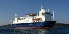
Two different but complementary technologies were tested aboard the NOAA vesselBay Hydrographerin an effort to find a more efficient, higher accuracy and safer alternative for traditional shoreline verification. Both systems performed well, were relatively easy to integrate into the existing hydrographic suite of equipment and provided a means of positioning various items from a boat at a safe distance offshore. The OCR capabilities of the videogrammetry system have great productivity potential for surveying port facility infrastructure. The long-range laser system holds promise for those areas where the shoreline structure is entirely natural and items such as rocks and islets dominate the survey. Each provides benefits where the other is weakest (i.e. using the video to classify features in the point cloud for which there may be insufficient data).??Thefinal result of this experiment is the production of what will inevitably become the nautical chart of the future, a merge of previously acquired Norfolk Harbor airborne laser data with the vessel-based laser data. The 2D rendering in Figure 4 does not do it justice; however, the picture is still quite stunning. Visualisation in three dimensions, on a high-definition colour monitor is truly impressive.
Acknowledgements
Thanks to the crew of theBay Hydrographer, Briana Welton and Mike Davidson, Catherine Morin and Antonio Silva from Geo-3D, Bruce Francis from Applanix, and Jason Woolard and Jon Sellars from the NOAA’s National Geodetic Survey.
Any mention in this article of a commercial product is for informational purposes and does not constitute an endorsement by the US Government or any of its employees or contractors.
Note from the Editor
This article is based on a presentation on this subject at Hydro ’07 and is published here with the kind permission of the organisers.

Value staying current with hydrography?
Stay on the map with our expertly curated newsletters.
We provide educational insights, industry updates, and inspiring stories from the world of hydrography to help you learn, grow, and navigate your field with confidence. Don't miss out - subscribe today and ensure you're always informed, educated, and inspired by the latest in hydrographic technology and research.
Choose your newsletter(s)