Underwater Recovery Operations off Sharm el-Sheikh
This article covers the recovery operations that took place after the accident on 3 January 2004 off Sharm el-Sheikh that involved a Boeing 737-300 operated by Flash Airlines from Sharm el-Sheikh, Egypt to Paris, France. The plane crashed into the Red Sea approximately six nautical miles southwest of the airport. In this article, the emphasis is on the preparatory work needed prior to committing costly resources and on the subsequent steps (locating and recovering the flight recorders, mapping the wreckage, recovering aeroplane parts, etc.).
Recovery operations took place from 3 January to 5 February 2004.
Safety investigators from Egypt, France and the USA, as well as Egyptian and French seamen, worked as a team during the recovery operations that represented the first phase of the investigation.
Naval Resources
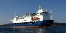
The French Navy mobilised considerable resources such as the frigate Le Tourville and the fleet support vessel La Somme. In addition, the French government chartered two salvage ships equipped with underwater robots, the Ile de Batz and Janus II, to complete this operation. The Scorpio ROV (work class, see Figure 1), provided by France Télécom Marine, was installed with its 50 tonnes of equipment on the Ile de Batz, owned by Alcatel (LDA).
The Janus II, owned by Comex, supports the Super Achille ROV (observation class), which can be remotely controlled via its lifting cable from the Janus II. Once at its working depth, Super Achille exits a ‘garage’ cage, attached via a 70 metre floating cable and controlled by a winch at the top of the cage (Tether Management System). This gives the robot mobility by not hindering its movements through the drag from around a thousand metres of connecting cable.
Hydrographic Information
Before committing the naval resources, it was essential to get more information on the wreckage site and especially its depth. Parts that were found floating on the surface and the initial witness statements collected were not sufficiently precise to allow the wreckage of the plane to be located. Moreover, the seafloor was not thoroughly charted and varied in depth between 100 and 1,420 metres over relatively short distances. The French Navy sent the oceanographic ship, the Beautemps-Beaupré, to carry out a multi-beam sonar hydrographic survey of the accident area. It drew up a bathymetry of the seafloor with 50-metre isobaths.
Initial Means Used to Locate the Recorders
A commercial aeroplane is equipped with a cockpit voice recorder (CVR) and a flight data recorder (FDR). When immersed under water they can be located by the signals (1 bip/second with 37.5kHz (±1kHz)) transmitted by the beacon (pinger). This pinger, attached to each recorder, is designed to transmit this signal for at least 30 days. The French Navy used an acoustic detector assembled on a pole called ‘Helle’ which tracks signals on frequencies ranging from 7 to 50kHz. This detector has two reception antennae, one multidirectional and the other directional.
Zooming in on the Echo
The first stage in the search consisted of checking signal transmissions and defining a general area using the multidirectional antenna. On 5 January, the French Navy heard a very weak echo (point 1 on Figure 2) to the north of the last validated radar position recorded (point R). The following day they detected a second echo further south (point 2). As the seafloor was uncharted at that time, locating the beacons was complicated by possible reflections from the transmitted sound waves and possible secondary echoes. The next stage consisted of taking successive bearings using the directional antenna so as to get a more precise fix. During this triangulation, they discovered a third echo (point 3). The position of this third echo was considered as nominal since it could be picked up from all bearings. It became the reference for ROV operations and was called ‘point zero’. The measurements and calculations performed gave an estimated depth of the recorders at around one thousand metres.
Use of a GIB System
To narrow the search area, the French Navy contracted ACSA to supply a GIB system (GPS Intelligent Buoys). For the purposes of the investigation, they adapted a network of four acoustic receivers to conduct a search at a depth of around one thousand metres. The hydrophones, immersed 450 metres down around the initial identified position, drifted with the current while continuously transmitting information on their position and any signals received (Figure 3). An algorithm integrated all data to determine the recorder’s fixed position. In theory, this new location was accurate to within 10 metres.
The Flight Data Recorder
The Scorpio robot started searching for the recorders based on the coordinates of ‘point zero’ contained inside the green circle of Figure 4, which illustrates a precision of around 100 metres. This position was then refined by the ACSA system, which produced a theoretical position approximately 70 metres further south (blue circle) with a precision of +/- 10 metres over 100 metres. By dividing the accuracy radius by ten, the search area was divided by one hundred. A square of 20 by 20 metres was then defined and systematically searched by the ROV. On 16 January 2004, while finishing one run, this visual search rapidly led to the FDR. The use of a GIB system proved to be essential in this context since the ROV only used visual means to search for the recorders and could not be guided by acoustic information to home in directly on the pingers.
The Cockpit Voice Recorder
The search for the CVR required making some further tactical choices. Since the beginning of the operations, the echo from the second pinger had appeared to be located a few hundred metres north of the initial search area (point 2 of Figure 2). At that time, results from ACSA computations were not yet available. For accidents with high impact forces, accelerations at the time of the collision may separate the pinger from the recorder case. This assumption was considered plausible on the basis of the initial analysis of wreckage distribution. It was decided to define a zone to the south of the position of the FDR. The CVR was found approximately 24 hours after the finding of the FDR, just outside the search area designated by the investigators. Its case was damaged more than the FDR’s; the pinger had separated.
Mapping the Wreckage
Exploration of the seafloor was organised by defining rectangular zones extending outwards from the central area. Each zone was then divided into grids with the side of each square being 3 to 5 metres, depending on the ROV used and the specific objectives. During these operations, it was important to have aeronautical specialists who were able to coordinate the search and identify the debris. The various parts located and identified during the dives were entered in a database. Parameters such as the date, the position, a brief description and photographic references (e.g. digital stills from the Super Achille) provided useful information for the investigation.
Wreckage Distribution
Figure 5 shows the wreckage distribution contained in a rectangle of 440 by 275 metres. It is compatible with the last recorded heading (311 degrees) and the northeast current measured by the Beautemps-Beaupré. The heavy parts (engines and main landing gear) were close to the point of impact whereas lighter debris drifted with the prevailing current during its thousand metre descent.
Recovery of Aeroplane Parts
The strategy for aeroplane parts recovery was developed after initial flight recorder readouts undertaken in Cairo. All parts related to aeroplane control surfaces, flight systems and flight deck panels were regarded as priorities. The work performed jointly by the Janus II and the Ile de Batz (both with dynamic positioning) made it possible to recover large parts such as the rudder and the elevator (Figure 6).
All salvaged parts were preserved in seawater until unloading at the naval port of Sharm el-Sheikh and handover to the Egyptian authorities.
Figure 7 combines airfield data, bathymetric data, the theoretical trajectory (in yellow) and the aeroplane track (in red) from the FDR readout.
Conclusion
Thanks to the preparatory work undertaken by the French Navy, the recorders were recovered in less than two weeks although they were in a relatively uncharted area about a thousand metres deep. The logistical support, which greatly facilitated teamwork, was a significant part of the success of the operations. The Navy’s decision to deploy the ACSA system contributed greatly to reducing the time the search took.

Value staying current with hydrography?
Stay on the map with our expertly curated newsletters.
We provide educational insights, industry updates, and inspiring stories from the world of hydrography to help you learn, grow, and navigate your field with confidence. Don't miss out - subscribe today and ensure you're always informed, educated, and inspired by the latest in hydrographic technology and research.
Choose your newsletter(s)