S-44 and the systematic error
A relevant but often overlooked aspect of uncertainty
IHO standard S-44 is often used (or misused) to specify the quality of a hydrographic survey. While it is a useful tool, it is easy to misinterpret. One ‘misuse’ is to apply the IHO orders directly to non-safety of navigation, as explicitly stated in Chapter 1. Another aspect that is overlooked is the systematic error part of the uncertainty, as S-44 only states that “The equipment should be free of systematic errors which must be determined by calibration and qualification” (B.2). The systematic error is however in general not zero and very important in, for example, dredging surveys.
Systematic error and TVU/THU
S-44 and the associated survey orders define the total vertical uncertainty (TVU) or total horizontal uncertainty (THU) as a combination of errors, rather than separating them into specific errors. This seems logical for safety of navigation, as it is irrelevant which error produces the uncertainty for a shallowest depth.
On the other hand, dredging and stone placement are usually measured in terms of layer thickness or volume. For this, the standard IHO orders are not directly suitable. For example, Exclusive Order surveys in 15 metres of water depth result in a TVU of 0.19m. As the error is not specified any further, a significant part of this error could be attributed to systematic error, especially when operating a well-calibrated RTK + MBES system. For these systems, the random part of the error (precision) is probably somewhere between 0.03m and 0.10m in these conditions.
To remedy this, it is possible to specify your own ‘Dredging Order’ using the matrix set-up in S-44. Using the lowest values in the matrix gives a TVU of 0.06m [a = 0.05m (Bc14); b = 0.002m (Bd10)]. This might be hard to achieve concerning the random error but should help to reduce the systematic error. As an alternative, the author often uses a more detailed approach when working on dredging and stone placement projects. In the specification, the TVU for Special or Exclusive Order is stated with an additional specification, which states that the systematic error component of the TVU should not exceed x metres, where x depends on the type of project and accuracy of the volumes to be obtained.
As shown, the systematic error component of TVU (and THU) is important but still often neglected in specifications as well as most a priori tools. Theoretically, the systematic error of a well-calibrated survey vessel should be zero, but seldom is in the real world.
Classification of systematic errors
Various error sources create a small, but sometimes significant, systematic error. Depending on how we use the survey system we might be more interested in the relative systematic error or in the absolute systematic error. The absolute systematic error is the systematic offset or bias against a known true value or reference datum. A relative systematic error is the error found between two consecutive surveys of the same area with the same equipment (and settings) on the same vessel.
We also need to consider the spatio-temporal variations in some systematic errors. These are errors that may cancel out over a long time or area (and could be classified as a random error) but are to be considered systematic for the finite duration or area of the survey. The various systematic errors can be classified as:
- calibrations and offsets
- geodetic
- environmental
- instrument
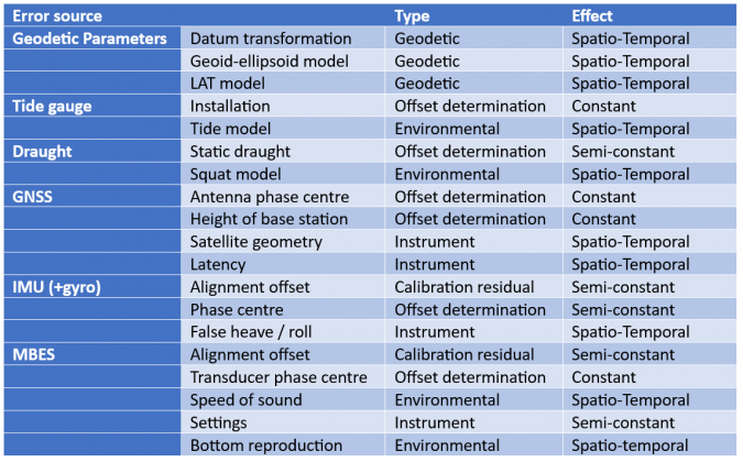
Table 1 details various errors and their type of behaviour.
Residuals from offset determinations and calibrations
The results of dimensional control measurements or equipment calibrations are often stated with a precision. Most a priori tools (and users) will state these as a random error. This is not correct in the author’s opinion. The coordinates or offsets are entered as fixed numbers and thus do not change during the survey, and are therefore systematic. With proper dimensional control and calibrations, the probable error is often small but it may still be significant. If the 95% uncertainty of any node in the Vessel Reference Frame is for example 5mm, the total systematic error could be anywhere between -10mm to +10mm with a 95% certainty. Statistically speaking, 7mm would be a reasonable approximation in this case. When using the same vessel (and settings) for in- and out-survey, the volume or layer thickness error is zero. There is therefore an effect on absolute depths.
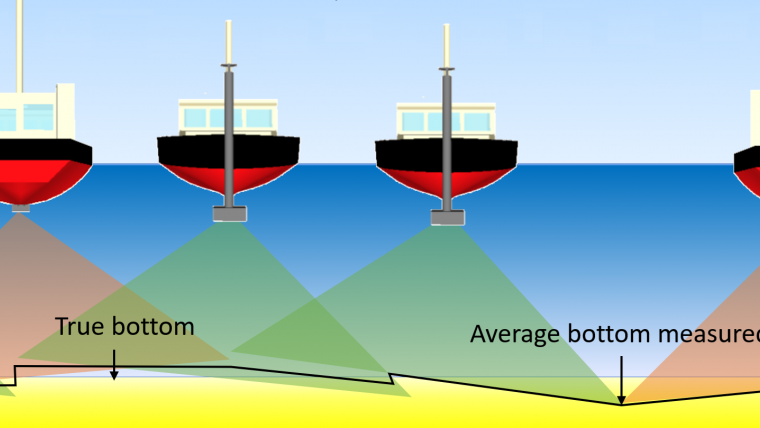
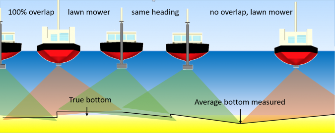
Calibration residuals follow the same pattern. For example, a patch test yields a residual roll calibration error with an uncertainty. The number is again entered as a fixed value and does not change during the survey. This causes one side of the swath to be systematically too high and the other side systematically too low. As volumes are based on averages, the final effect depends on the amount of overlap and track heading (Figure 1). As the effect depends on how lines are sailed, there is an effect on both relative and absolute systematic error.
For the IMU, the effect of a residual calibration offset depends on the lever arms and vessel heading. The residual offset causes the antenna and echosounder to have an incorrect position and height. Theoretically, the effects are also dependent on the vessel motion; however, as both actual vessel motion and residuals are very small in a well-calibrated IMU, the effect on the survey results is then limited.
Errors in references and conversion parameters
Datum transformations are typically stated with an accuracy in the EPSG registry. Similarly, a vertical datum model such as a geoid-ellipsoid separation model or LAT model has a certain accuracy. The errors in both are probably zero on average over the entire model or transformation. However, locally they usually have a constant and possibly non-zero error. When using the same settings and software for in- and out-survey, the effect on volumes and layer thickness cancels out. Again, for absolute depths there is therefore an effect.
Environmental errors
Environmental systematic errors have causes outside of the survey set-up. A large source is the use of water-level corrections rather than GNSS heights. Tide gauges measure the tide in a specific place, but in other places the water level will be different, resulting in a systematic offset for that area. Similarly, a correction for the dynamic and static draught of the vessel will contain some element of systematic error, especially if no squat/settlement model is employed. The effects can range from almost nothing to decimetres. The use of accurate GNSS heights cancels out most of these errors.
Sound velocity is another cause of environmental systematic errors. Sound velocity changes between profiles. Even when using a moving profiler or an alert to ensure that profiles are taken regularly, there is a slowly increasing error. When using a very common check between the SV Sensor near the transducer and the corresponding value from the profile of 2m/s, the effect will increase to around 0.02m in 15 metres of water depth just before a new profile is taken. While the effect will be small for short surveys in stable water conditions, it can be significant for longer surveys or in highly dynamic waters such as estuaries.
Instrument error
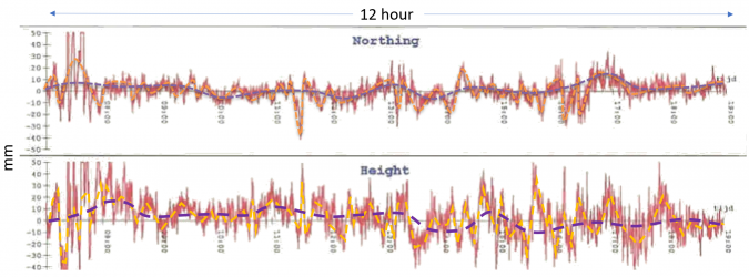
GNSS itself is also not free of some kinds of systematic error. Over a short time, GNSS often seems to give very stable positions. Tests have shown that over a period of 15–30 minutes there is a slowly varying height in PPP and RTK, which can have an amplitude of several millimetres up to a few centimetres (Figure 2). This is the result of satellite geometry and the changing (electronic) phase centre of the antenna. Depending on the size of the area, this results in a systematic error of a few millimetres.
The IMU is also a source of variable systematic errors due to false or induced heave, roll and pitch. These induced values will offset the measurements over a span of time lasting up to minutes after a significant change in speed or after a turn. These errors are significantly reduced for an IMU with speed and heading input. With GNSS, the effect of false or induced heave depends on the software.
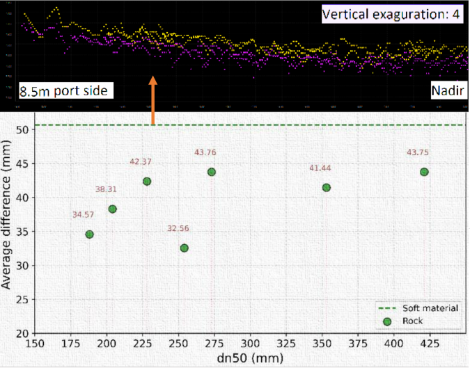
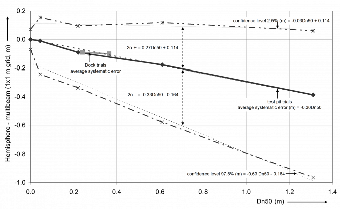
Finally, the echosounder settings can have a significant effect. A significant error can be caused by using different frequencies over a soft bottom. Tests have furthermore shown that longer pulse lengths can lead to a deeper bottom (Figure 3). Finally, the levels as obtained with a multibeam over armourstone differ from those obtained with the common reference above water (spherical foot staff), leading to differences in obtained levels, layer thickness and volume of centimetres to decimetres depending on the size of the armourstone (Figure 4).
Conclusion
As shown, there are many errors that do not cancel out. A posteriori checks on dredging works by the author have shown the relative residual systematic error to be anywhere between roughly 0.01 and 0.05 metres. The absolute systematic error may be much higher but is harder to establish. It was also shown that it is very hard to work these systematic errors into an a priori computation, as results also depend on the environment. Maximum values could be established for the main components by considering a worst-case scenario. It is recommended to specify the maximum allowed systematic error on dredging and construction projects separate from the TVU and to require a procedure to test these before the survey commences.
Finally, the recommendation of performing the in- and out-survey on dredging and construction projects with the same vessel and same settings is repeated here. This will still give a systematic error but should reduce the error in obtained layer thickness and volume. There will however still be an effect on absolute depths.

Value staying current with hydrography?
Stay on the map with our expertly curated newsletters.
We provide educational insights, industry updates, and inspiring stories from the world of hydrography to help you learn, grow, and navigate your field with confidence. Don't miss out - subscribe today and ensure you're always informed, educated, and inspired by the latest in hydrographic technology and research.
Choose your newsletter(s)