4D Subsea Sonar Usage at Alvheim
Complementing Conventional Surface Survey of GPS and USBL Buoy Tracking
At the Alvheim oil and gas field, surface and subsea positioning services were used during the installation of the Alvheim floating, production, storage and offloading vessel.
View Larger Map
The surface positioning was provided by Fugro Survey AS using their Starfix.HP and SkyFix-XP high precision DGPS positioning systems. These two state of the art systems utilise GPS carrier phase computational techniques combined with carrier phase corrections from the Fugro Reference Station Network (Starfix.HP) and orbit and clock corrections from the NASA/JPL Reference Station Network (SkyFix-XP) to compute positions with a decimetre accuracy.
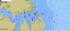
The Alvheim oil and gas field is operated by Marathon Petroleum Norge AS, a wholly owned subsidiary of Marathon Oil Corporation. Marathon awarded Fugro Survey AS the main contract for the surface and subsea positioning services. The Alvheim oil and gas field is located off the Norwegian coast at a water depth of 120 metres (Figure 1). The oil and gas production will be from a floating, production, storage and offloading (FPSO) vessel that has an overall length of 252 metres. The tank capacity provides for 580,000 barrels of oil.
FPSO Vessel
The oil will be offloaded to shuttle tankers for export. The vessel is passively moored by 12 lines in an arrangement designed to withstand a 100-year storm with a 14.6 metres significant wave height. The turret and mooring system (Submerged Turret Production, STPTM) was delivered by Advanced Production and Loading AS (APL). A total of 14 slots through the turret accommodate risers and umbilicals for the initial subsea wells and for planned expansions. The core of the STPTM system is the buoy moored to the seabed. Pulled into and secured in a mating cone at the base of the vessel forward moonpool, the buoy connects the vessel to the mooring system. Internal in the buoy is the turret with the connection to the mooring and riser systems. The outer buoy hull can rotate freely with the vessel around the turret by means of internal turret bearings.
Real-time Monitoring
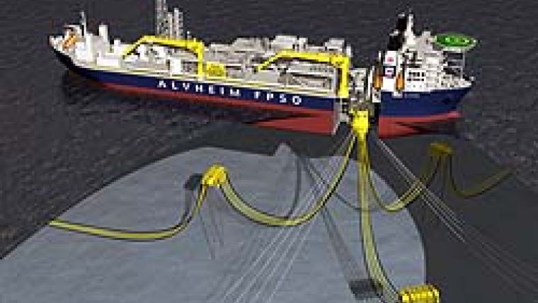
During installation in the field, the turret had to be pulled into the mating cone. The vessel was positioned by four tugs on dynamic positioning and through use of a tug management system. The pull-in was performed by a winch mounted on the Alvheim vessel with a rope reaved through the buoy. As the vessel moved due to waves and positioning by tugs, etc., it was important that the top of the turret was monitored in real-time in order to decide when the pull-in could take place. During the planning stage, concerns were made regarding the robustness of an ultra-short baseline (USBL) tracking system this close to the FPSO vessel hull. The concerns about the performance of the USBL system were due to the close proximity of the buoy top (±6m) to the hull of the vessel. This could have caused spurious signals from reflections off the hull. In addition, the USBL transceiver was located on a remotely operated vehicle (ROV) adjacent to the FPSO. We therefore decided to investigate alternative methods of locating the buoy top relative to the mating cone in case of USBL inaccuracies or the link failed between the ROV and the positioning team onboard the FPSO. Figure 2 shows the Alvheim FPSO and the buoy with the turret positioned within the mating cone.
4D Sonar
In order to guide the pull-in process, the x,y,z positions of the turret relative to the mating cone had to be known with high accuracy - not only in order to make a decision on when to start the pull-in operation, but also in order to monitor the actual pull-in. Therefore a system capable of delivering 3D position data in real-time had to be used. The Echoscope 4D sonar is such a tool. The echoscope complemented the conventional survey spread consisting of GPS surface navigation and USBL tracking of the buoy. The term 4D is used because the sonar generates 3D data in real-time - i.e. at a rate of about 13 data sets per second at ranges up to about 40 metres. The Echoscope has a range resolution of 4cm and a lateral resolution of 1°, which translates to 12cm lateral resolution at a range of 7m.
Echoscope Views
The Echoscope display can be split into three views as shown in Figures 3 to 5, enabling the operator to observe the scene from three different viewpoints simultaneously. The Echoscope software has the capability of showing 3D objects together with real-time sonar data, and so a simple model of the mating cone was used in order to show the position of the buoy relative to the mating cone. As the 4D sonar delivers 3D data in real-time, all echoes have known positions. Therefore the position of the buoy relative to the mating cone could actually be measured in metres, as shown in Figures 3 to 5. Note that the x-y plane is horizontal with positive x pointing forward along the axis of the vessel, positive y pointing starboard and positive z pointing downward.
First Use
Marathon understands that the Alvheim FPSO project was the first use of the Echoscope 4D for a buoy pull-in. Normally, APL recommend the use of ROVs to monitor the alignment of the buoy top to the mating cone. However, we were concerned about the very short pull-in distance and the size of the buoy relative to the perspective gained from the ROV cameras, i.e. the ability to confirm alignment. A downward-looking sonar device located in the cone was the best solution. Of interest, we did have ROVs monitoring the pull-in but the water visibility was very poor on the day and they contributed very little during the operation. The 4D sonar has been used previously on several construction projects and also on harbour security scanning. The Alvheim application was, however, particularly difficult due to severe acoustic reverberation (multi-path) caused by steel walls and smooth surfaces. These conditions are difficult to set up in a test environment, thus confidence in sensor performance and knowledge and experience of how to use it were critical to the success of the project. The fact that the 4D sonar generates a 3D image from a single pulse of sound makes the multi-path possible to handle.
Ideal Tool
Figure 3 (top of the series) shows the position of the buoy relative to the mating cone - obviously not ready to start the pull-in operation. As the buoy moved relative to the mating cone, the Echoscope display clearly showed the geometry; this can be seen in Figure 4 (middle), where the buoy was much closer to the mating cone. When the buoy top was aligned with the mating cone, the pull-in operation was allowed to commence. The pull-in operation (Figure 5, lower) was done in about 8 minutes and the entire operation was monitored in real-time. The application of 4D sonar has been demonstrated in a real-world environment and proved to be an ideal tool for monitoring critical underwater construction tasks. The authors believe that the technology has great potential within offshore construction in particular and within underwater operations in general.

Value staying current with hydrography?
Stay on the map with our expertly curated newsletters.
We provide educational insights, industry updates, and inspiring stories from the world of hydrography to help you learn, grow, and navigate your field with confidence. Don't miss out - subscribe today and ensure you're always informed, educated, and inspired by the latest in hydrographic technology and research.
Choose your newsletter(s)