Automatic detection of seafloor pipelines with deep learning
Trained for different scenarios
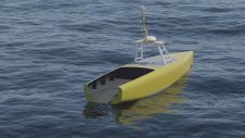
Seafloor pipelines are a critical infrastructure for oil and gas transport. Timely inspection is required to verify their integrity and determine the need for maintenance, as failures in these pipes may interrupt the vital distribution of oil and gas and cause environmental damage. The inspection of seafloor pipelines is a challenging task, however, due to their remote location and vast length. Autonomous underwater vehicles (AUVs) such as HUGIN, equipped with algorithms for pipeline detection and following, represent cost-effective innovations in these operations.
Autonomous pipeline inspection
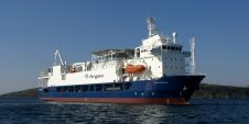
Traditionally, external pipeline inspection has been conducted with large and advanced offshore vessels applying towed or remotely operated vehicles (ROVs). The objective is to detect burial, exposure, free spans and buckling of the pipeline, as well as indications of damage due to third party activities, such as trawling and anchoring, and debris near the pipeline. During the last two decades, AUVs have emerged as a more efficient and less costly solution, as they are stable platforms that can travel faster (typically 3-5 knots compared to 1-2 knots for inspection ROVs) and operate without constant supervision from a mothership. Typical payload sensors for these AUVs include multibeam echo sounders (MBES), side-scan sonar and optical cameras.
To collect high-quality sensor data for inspection, the AUV must follow the pipeline at a specified cross-distance and height. Global position estimates from the vehicle’s inertial navigation system will not suffice, due to inevitable drift in the estimates over time and uncertainties in prior pipeline position data. One solution is the automatic detection of pipelines in the sensor data to provide real-time input to the vehicle’s control system, which then maintains the desired relative position and orientation (see flow chart in Figure 2). This is the basis for the PipeTracker system [1], cooperatively developed and refined since 2010 by the Norwegian Defence Research Establishment (FFI) and Kongsberg Maritime (KM). The PipeTracker applies traditional image analysis techniques to detect and track pipelines in sensor data from either side-scan sonar or MBES.

Sensor data
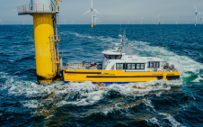
An MBES is an active sonar for bathymetric mapping of a swath centred below the AUV. The sensor estimates both the strength and time delay of the seafloor backscatter, providing the reflectivity and relative depth values. Figure 3 presents a pipeline data example collected with a HUGIN AUV (see Figure 1) in shallow water off the coast of Brazil, while Figure 4 presents a TileCam camera image of a corresponding subarea.
Through a collaboration between FFI, the University of Oslo and KM, we investigated how to use deep learning, described further in the next section, for the automatic online detection of seafloor pipelines in MBES data. To this end, we created and defined a method for annotating (labelling) pipelines in MBES data. Moreover, we tailored and extended existing state-of-the-art deep learning-based object detection techniques to this novel task and imaging format.
The dataset used is a collection of MBES images from 15 pipeline inspection missions gathered with different HUGIN AUVs by KM and FFI at various locations around the world.

Deep learning for pipeline detection
Deep learning refers to artificial neural network (ANN) models with many layers. Larger models coupled with increasing computational capabilities and huge amounts of data have led to the success of ANNs. In recent years, ANNs combined with deep learning has become the best performing method for countless data processing tasks, such as image classification, detection, tracking, speech recognition, synthesis, translation, the games Chess and Go, and many more.
With the impressive achievements of deep learning, we sought to tailor and test it on the pipeline detection task. To make the best use of deep learning, we looked to state-of-the-art methods on similar tasks. In particular, we looked to models that could detect and classify different objects in optical images. Processing and interpreting optical images are two of the early beneficiaries of deep learning, and have also spearheaded much of its progress. We then tailored the model, a combination of ResNet50 [2] and You Only Look Once (YOLO) [3], to the idiosyncrasies of the seafloor pipeline detection task and the MBES data format. Figure 5 illustrates our deep learning model.
Deep learning has two stages: training and inference. The training phase shows the model millions of examples of what we want it to do, and through this training phase, the model becomes increasingly better. After training, the model is expected to understand the general principle of the task and to work well on new unseen, similar examples. When the model is used to interpret new examples after the training phase, it is in inference mode. The performance in the inference mode is the measure of success of the model.

One key factor for a successful deep learning model is the data examples it trains on. To this end, we need to define and create labels that can supervise the model to learn its task. As existing deep learning models such as ResNet and YOLO do not support our data format and task, we created a tool to manually annotate pipelines in MBES data. These annotations defined the goal of the task, which is to automatically predict whether an MBES image segment contains seafloor pipelines or not, and where the detected pipelines are. In addition to data and labels, training an ANN requires formulating the task objective mathematically. Because of the peculiarities of the task and data format, we also proposed a novel seafloor pipeline detection task objective, the details of which are described in [4].
Results
We evaluated the trained model in two ways: (i) how well it predicted whether an MBES image segment contained a pipeline, and (ii) how precisely it located the top of pipelines. During testing, our model correctly predicted pipelines in over 85% of previously unseen cases; in other words, data examples that the model had not trained on. Moreover, the model also correctly located the pipelines with an on average less than two pixels offset to the labelled pipeline top, where pixels are pings and beams, interchangeably. For reference, the width of the pipeline in the depth channel of Figure 3 spans approximately five beams.

Conclusion and prospects
This work demonstrates that deep learning can effectively be used to detect pipelines in MBES data. Although traditional image analysis algorithms are already successfully used to detect seafloor pipelines, these are generally hand-designed and, to some degree, bespoke for the application. With deep learning, however, the model learns through training how to detect the pipelines in different scenarios. A deep learning model can often be improved simply by using more data examples. This means that detection performance can be improved over time as less common pipe configurations and environments are encountered – without the need for new algorithm development or refinement.
In further work, we will consider applying deep learning to detect seafloor pipelines in both side-scan sonar and optical images. Moreover, we envision using deep learning to evaluate the state of the pipeline in all the different sensor data, which would automate the inspection even further.

References
[1] Midtgaard, Ø., Krogstad, T.R., and Hagen, P.E., 2011, Sonar detection and
tracking of seafloor pipelines, Proceedings of the Underwater Acoustic
Measurements Conference, Kos, Greece, p. 9.
[2] He, K., et al., 2015, Deep Residual Learning for Image Recogni-
tion, arXiv: 1512.03385 [cs] [Online]. Available: http:
//arxiv.org/abs/1512.03385 (visited on 01/27/2022).
[3] Redmon, J., et al., 2016, You Only Look Once: Unified,
Real-Time Object Detection. arXiv: 1506 . 02640 [cs]. [Online]. Available: http : / / arxiv . org / abs / 1506 . 02640 (visited on 02/19/2022).
[4] Schøyen, V.S., Warakagoda, N.D., and Midtgaard, Ø., 2021, Seafloor Pipeline
Detection With Deep Learning, Proceedings of the Northern Lights Deep
Learning Workshop, vol. 2, Apr. 19, 2021. doi: 10.7557/18.5699.

Value staying current with hydrography?
Stay on the map with our expertly curated newsletters.
We provide educational insights, industry updates, and inspiring stories from the world of hydrography to help you learn, grow, and navigate your field with confidence. Don't miss out - subscribe today and ensure you're always informed, educated, and inspired by the latest in hydrographic technology and research.
Choose your newsletter(s)