Colouring the 'White Ribbon'
Strategic coastal monitoring in the south-east of England
A novel collaboration between maritime Local Authorities in south-east England is providing important new information on the coastal region to aid future decisions concerning the management of the coast.
The 'white ribbon', a term first coined by the British Geological Survey, is the well-known region spanning the land-sea interface. There is an equally well-known lack of data for this region: generally too shallow for most traditional bathymetric survey methods and too deep for land-based surveys. This inter-tidal and nearshore region is, however, of crucial importance to coastal engineers and managers, since land-based surveys alone will rarely encompass the entire volume of mobile sediment.
The Start
The Strategic Regional Coastal Monitoring Programme for the south-east of England was set up in August 2002 by the thirty-one maritime Local Authorities and the Environment Agency (Southern Region), thus extending from Portland Bill to the Isle of Grain in the Thames estuary. A first requirement was to establish a GPS Ground Control Network tied in across the whole region, using consistent geoid models and transformations. All survey data (bathymetric, topographic, ortho-photography and Lidar) uses this Control Network.
Nearshore Survey
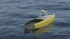
Our aim is to put some colour (data) into the ‘ribbon’, and this is achieved by overlapping land-based and bathymetric surveys. Where beaches are accessible they are surveyed by RTK GPS up to four times per year, with profiles ~100 to 200 metres apart. Topographic surveyors must reach the level of Mean Low Water Springs. A bathymetric survey of the entire 1000km of coastline was commissioned at the start of the Programme, to be repeated at five-yearly intervals. Surveys extend 1km from the shoreline with lines run at 50m intervals, with the exception of sites carrying ‘Do Nothing’ management status (e.g. hard rock cliff areas), which extend only 500m offshore with survey lines at 100m intervals. Surveys are conducted using a single-beam echo sounder. The bathymetric surveys must overlap the topographic surveys, and therefore the landward limit is generally one vertical metre above MLWS. Figure 1 illustrates our idea of a shallow-water survey.
Combining Data
Providing the bathymetric and topographic surveys have been conducted at around the same time, the profiles can be combined and the cross-sectional area of sediment above the bedrock calculated. The example in Figure 2 is from Bournemouth beach, which has a comprehensive and longstanding history of monitoring. The solid red line marks MLWS level (the traditional level used for calculating cross-sectional area) and it is clear that the highly mobile sub-tidal bar represents a considerable proportion of the mobile sediment which would remain unaccounted for without bathymetric survey.
Lidar and Bathymetry
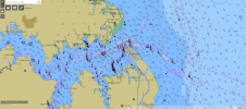
For the major harbours along the south-east coast, continuous cover through the inter-tidal and sub-tidal areas is achieved by combining bathymetric survey of the main harbour channels with terrestrial Lidar survey; the surveys are conducted using the same survey-control grid and can be combined spatially. The seaward limit for Lidar is slightly higher than MLWS due to the need to balance mobilisation costs and flight-window length. Even so, a reasonable overlap can be achieved, as shown in Figure 3 from Langstone Harbour. Bathymetric data is routinely sent to the UK Hydrographic Office. The recent nearshore bathy-survey of the Isle of Wight alone resulted in five new Notices to Mariners detailing previously uncharted shoals, and was able to confirm several soundings over which there were queries.
Beach Sediments
Further colour is added to the ‘ribbon’ by including information about beach sediment. Once every five years, and annually for Beach Management Plan beaches, a topographic baseline survey is conducted with profiles every 50m and continuous measurements along major contours. At the same time, the beach sediment type is logged for every data-point using a pre-ordained system of codes, and in this way sediment composition in the inter-tidal region of all accessible beaches in the region is measured every five years (see Figure 4). In addition, an aerial survey of the coastline is carried out annually, and every five years the photos are ortho-rectified.
Waves and Tides
Aside from survey and sediment composition data, the ribbon is equally ‘white’ with information about the shallow-water wave conditions where, traditionally, there is a dearth of long-term measurements. To try to fill this gap, a network of wave and tide recording equipment has been deployed, including seven Datawell Directional WaveRider Mk III buoys situated in approximately 10m CD water depth, supplemented by inshore wave and tide measurements and some meteorological stations. Data from the buoys is streamed to the website in near real-time and used operationally (for flood warnings, notification of high-wave conditions, threshold conditions for initiating post-storm topographic surveys and for calculating down-time for coastal schemes or bathymetric surveys), with text messaging to local-authority coastal engineers. In the longer term, the wave parameters are used for extremes-analysis, to obtain return periods and wave climates in the nearshore region.
Data Availability
All data is rigorously quality-controlled and archived, together with an extensive metadata form. All data collected by the Regional Monitoring Programme is freely available and can be downloaded directly from the website’s Online Viewer and Data Catalogue (www.channelcoast.org). The ortho-photography and the Lidar data are proving particularly useful for other applications, such as mapping the extent and condition of inter-tidal ecological habitats, like salt marshes.
Data Analysis
Once gathered, the different strands of data are analysed in a similar manner across the whole region, based on coastal process sub-cells, for instance Poole Bay, rather than restricting analysis to municipal boundaries. The results are generally presented on GIS maps, with a backdrop of the most recent ortho-photo, another benefit of a common survey-control network. A DTM is produced for each survey, followed by a variety of difference models, including the most recent survey minus the last survey, and the most recent minus a baseline survey such as post-replenishment, to show how the beaches are responding over longer time-scales. This comparison with a baseline survey is an important one, as small changes each year can seem negligible but over five years can represent significant erosion. Figure 5 shows an example of a difference model around North Point (Hurst Spit), where blue represents areas of accretion and pink/red areas of erosion.
The Future
As with most monitoring data, the measurements become increasingly useful the longer the coverage of the dataset; and this level of coastal monitoring in the south-east of the UK will continue until 2012 at least. Furthermore, a similar regional monitoring programme has been approved for the south-west of England, stretching from Portland Bill to Minehead, and will get underway in April 2006.

Value staying current with hydrography?
Stay on the map with our expertly curated newsletters.
We provide educational insights, industry updates, and inspiring stories from the world of hydrography to help you learn, grow, and navigate your field with confidence. Don't miss out - subscribe today and ensure you're always informed, educated, and inspired by the latest in hydrographic technology and research.
Choose your newsletter(s)